POWER DISTRIBUTION
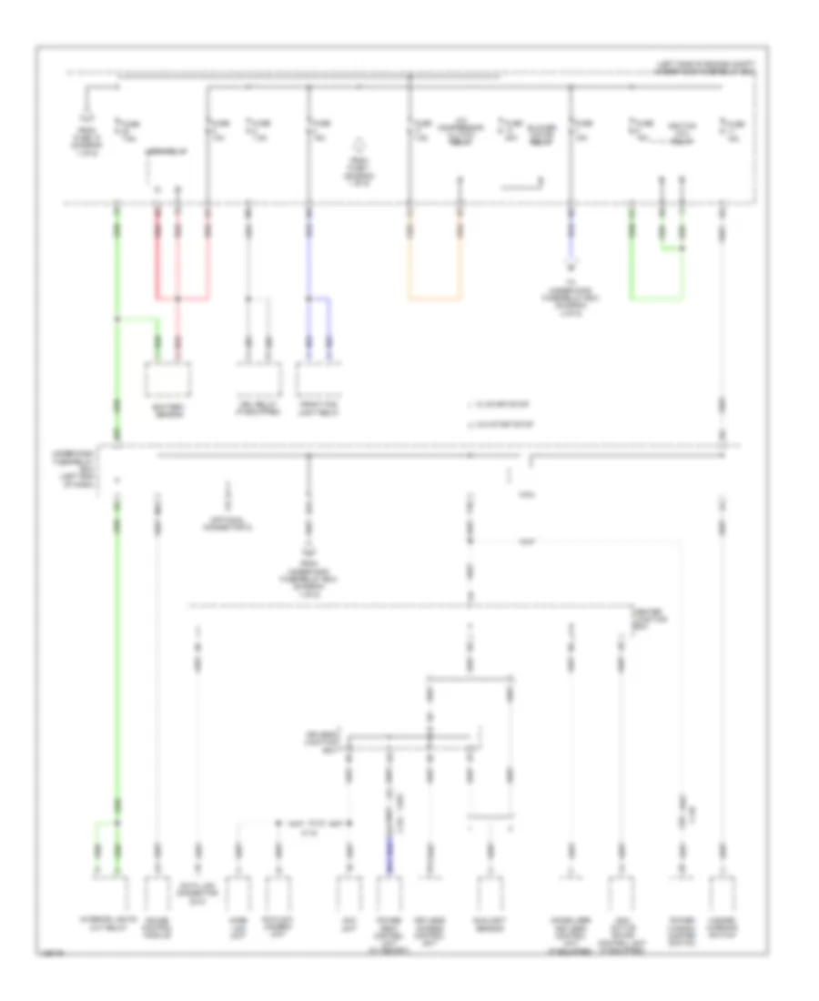
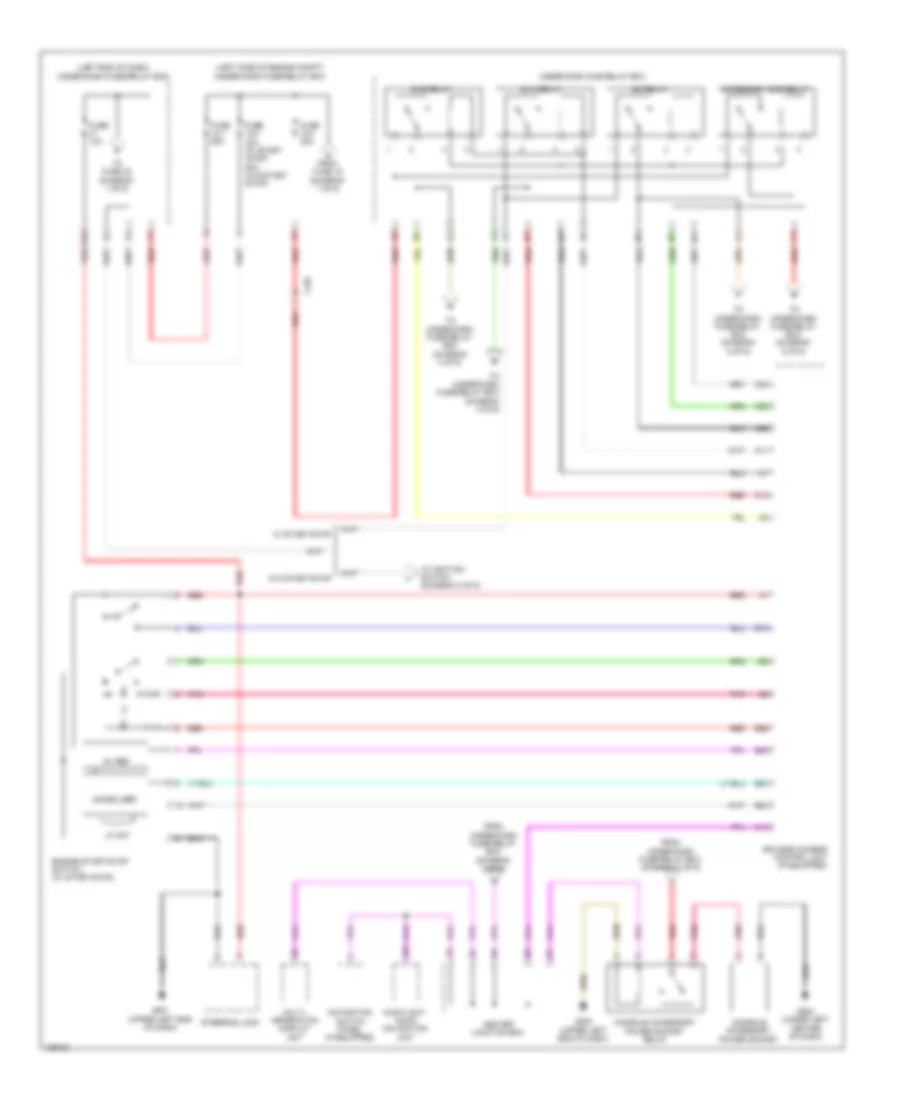
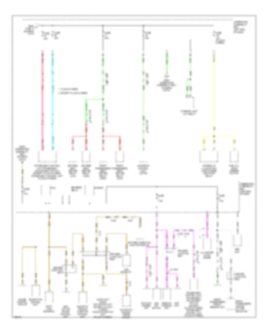
Power Distribution Wiring Diagram, Except Hybrid (1 of 6) for Honda Accord Hybrid Plug-In 2014

List of elements for Power Distribution Wiring Diagram, Except Hybrid (1 of 6) for Honda Accord Hybrid Plug-In 2014:
- (left end of dash) under-dash fuse/relay box
- (left side of engine compt) under-hood fuse/relay box
- (right center of dash) j/c c001
- 2.4l m/t
- A/c condenser fan relay
- Alternator
- Audio unit/ audio navigation unit
- B10
- Battery
- Battery sensor
- Brake light relay (touring)
- Brake pedal position switch
- C107
- C109
- C110
- C112
- C122
- Driver's power lumbar support switch
- Eld
- Eps control unit
- Etcs control relay
- Except 2.4l m/t
- Except sport
- From fuse 31 (diagram 6 of 6)
- Front passenger's power window switch
- Fuse 10a
- Fuse 12-10 30a
- Fuse 12-2 40a
- Fuse 12-5 30a
- Fuse 12-6 30a
- Fuse 12-7 30a
- Fuse 12-8 30a
- Fuse 12-9 30a
- Fuse 125a
- Fuse 15a
- Fuse 2-1 70a
- Fuse 2-2 60a
- Fuse 2-3 40a
- Fuse 2-6 40a
- Fuse 2-7 30a
- Fuse 20a
- Fuse 40a
- G1 (left front of engine compt)
- Headlight low beam relay
- Injector relay (2.4l)
- Lock relay
- Magnetic switch
- Micu
- Multi- information display unit
- Pgm-fi main relay 1
- Pnk
- Power window master switch
- Power window relay (sedan)
- Radiator fan relay
- Rear window defogger relay
- Red
- Relay circuit board
- Starter
- Starter cut relay 1
- T101
- Tail light relay
- To fuse 12-4 (diagram 6 of 6)
- To fuse 20 (diagram 2 of 6)
- To fuse 4 (diagram 2 of 6)
- To fuse 40 (diagram 5 of 6)
- To under-dash fuse/relay box (diagram 2 of 6)
- To under-dash fuse/relay box relay (diagram 3 of 6)
- To under-dash sub fuse box (diagram 5 of 6)
- Trunk lid actuator relay
- Under-hood fuse/relay box (left side of engine compt)
- Unlock relay
- Unlock relay (dr)
- Vsa modulator control unit
- Windshield washer main relay
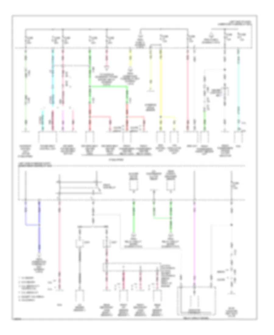
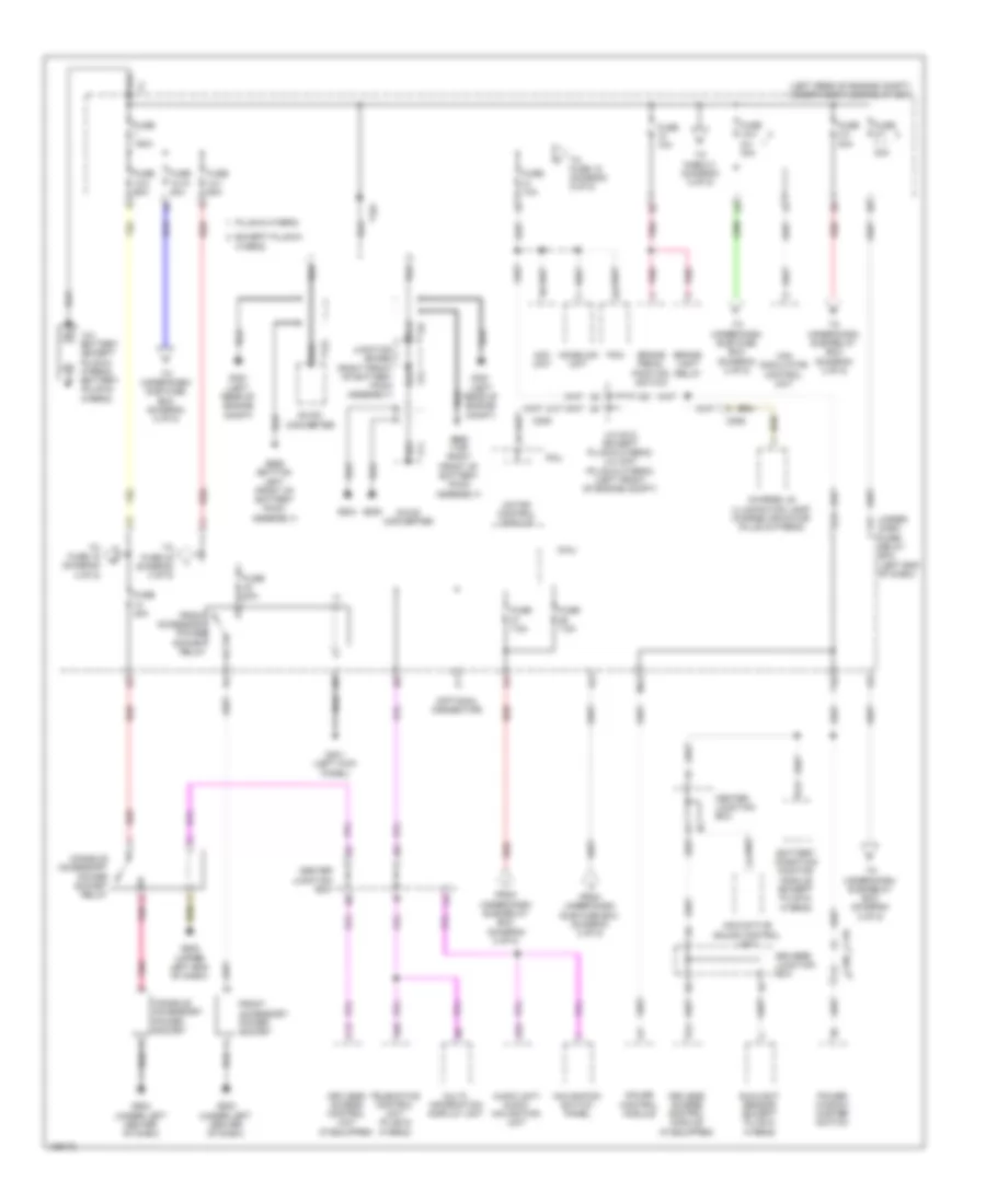
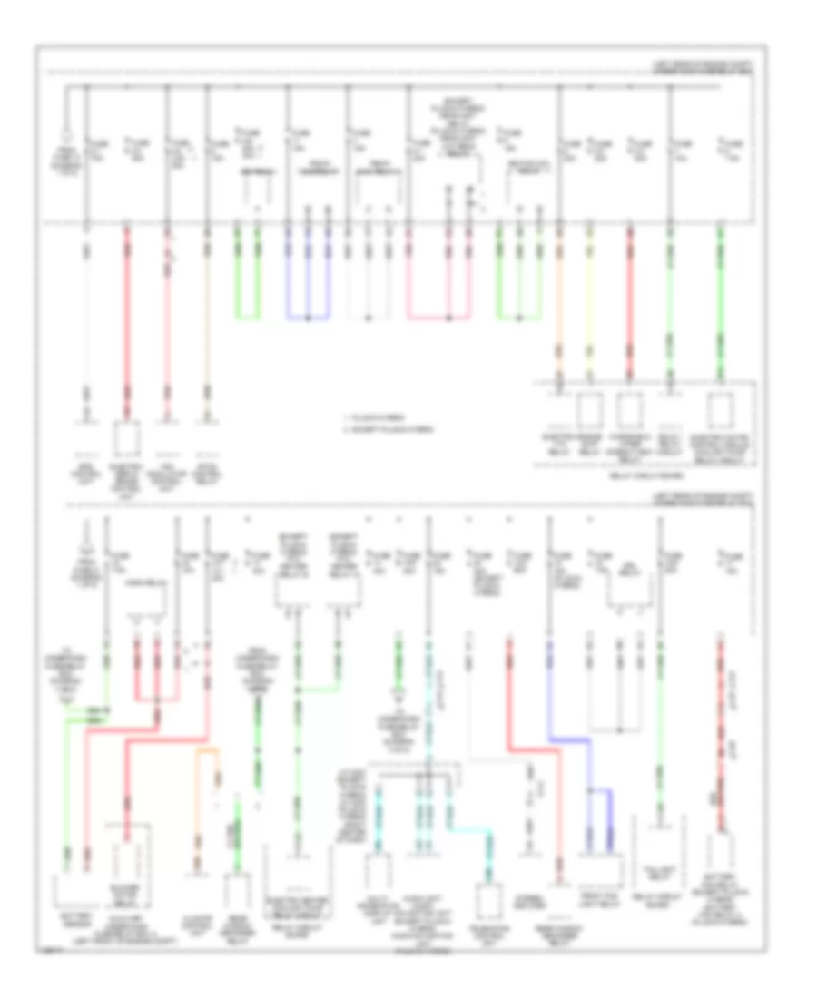
Power Distribution Wiring Diagram, Except Hybrid (2 of 6) for Honda Accord Hybrid Plug-In 2014
List of elements for Power Distribution Wiring Diagram, Except Hybrid (2 of 6) for Honda Accord Hybrid Plug-In 2014:
- (left side of engine compt) under-hood fuse/relay box
- (optional connector c)
- A/c compressor clutch relay
- Acc unit
- Anc/ active sound control unit (if equipped)
- B11
- B14
- Battery sensor
- Blower motor relay
- C109
- C110
- C115
- C122
- Center junction box
- Data link connector (dlc)
- Driver's junction box
- Drl relay (if equipped)
- E18
- E23
- Fcw/ldw camera unit
- From fuse 1 (diagram 1 of 6)
- From fuse 18 (diagram 1 of 6)
- From under-h00d fuse/relay box (diagram 1 of 6)
- Front fog light relay
- Fuse 10a
- Fuse 15a
- Fuse 40a
- Fuse 7.5a
- Gauge control module
- Hazard warning switch
- Home link unit
- Horn relay
- Ignition coil relay
- Immobilizer keyless control unit (if equipped)
- Interior lights cut relay
- Keyless access control unit
- M12
- Micu
- Power seat control unit (w/ memory)
- Power window master switch
- Red
- Sunlight sensor
- T10
- To under-hood fuse/relay box (diagram 3 of 6)
- Under-dash fuse/relay box (left end of dash)
- W/ start/stop
- W/o start/stop
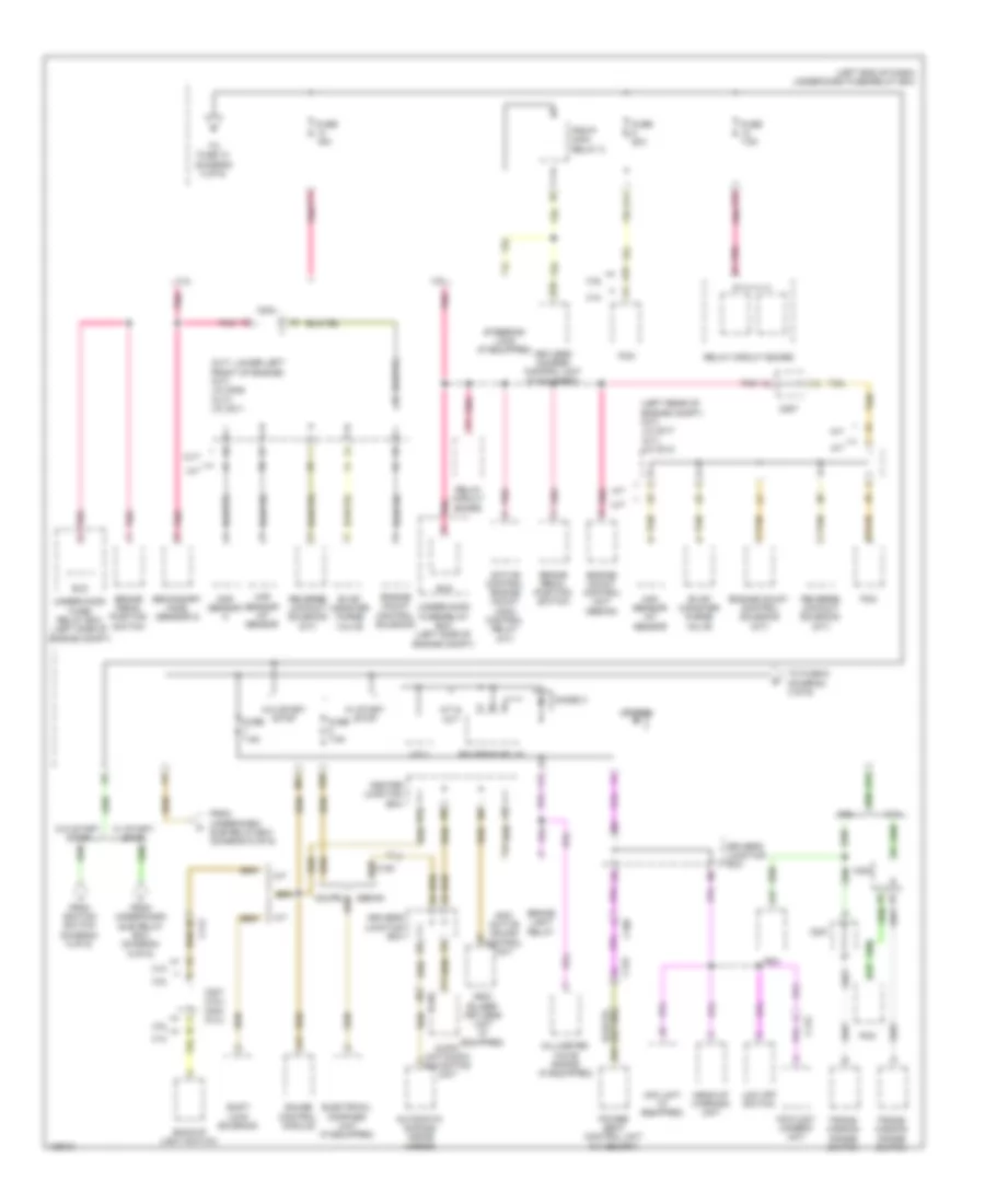
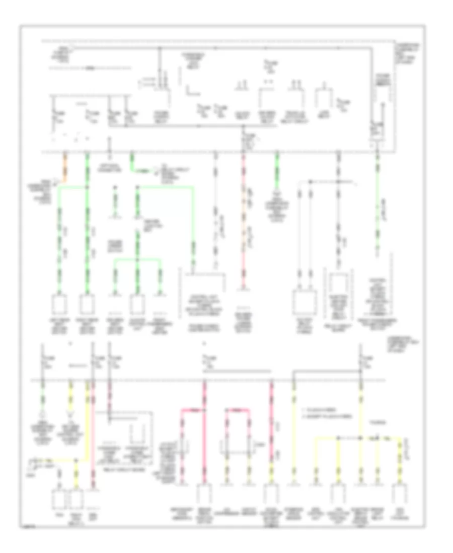
Power Distribution Wiring Diagram, Except Hybrid (3 of 6) for Honda Accord Hybrid Plug-In 2014
List of elements for Power Distribution Wiring Diagram, Except Hybrid (3 of 6) for Honda Accord Hybrid Plug-In 2014:
- (if equipped)
- (left end of dash) under-dash fuse/relay box
- (left side of engine compt) under-hood fuse/relay box
- 2.4l
- 2.4l sedan a/t
- 2.4l sedan cvt,
- 3.5l
- A/c compressor clutch relay
- A/f sensor (sensor 1)
- A11
- A12
- A14
- A16
- A38
- A39
- Blower motor relay
- C104
- C105
- C109
- C112
- C121
- C122
- C126
- C204
- C207
- California
- Center junction box
- Coupe
- Coupe & 3.5l
- Driver's power seat adjustment switch
- Driver's seat heater relay (high)
- Driver's seat heater relay (low)
- E10
- E26
- Eps control unit
- Evap canister vent shut valve
- Except california
- From fuse 13 (diagram 4 of 6)
- From fuse 5 (diagram 4 of 6)
- From relay circuit board (diagram 5 of 6)
- From under-hood fuse/relay box (diagram 1 of 6)
- From under-hood fuse/relay box (diagram 2 of 6)
- Front a/f sensor (bank 2, sensor 1)
- Front passenger's air bag cutoff indicator
- Front passenger's heater relay (high)
- Front passenger's heater relay (low)
- Front passenger's weight sensor unit
- Front secondary ho2s (bank 2, sensor 2)
- Fuse 10a
- Fuse 20a
- Fuse 7.5a
- J/c c014 (california) j/c c016 (except (california) (sedan: right front of engine)
- Moonroof control unit/ motor
- Pcm
- Pgm-fi sub relay
- Pnk
- Power seat control unit
- R13
- R14
- Radiator fan relay
- Rear a/f sensor (bank 1, sensor 1)
- Rear secondary ho2s (bank 1, sensor 2)
- Rear window defogger relay
- Red
- Relay circuit board
- Sedan
- Srs unit
- Steering angle sensor
- To console accessory power socket relay (diagram 6 of 6)
- Vsa modulator control unit
- W/ memory
- W/o memory
Power Distribution Wiring Diagram, Except Hybrid (4 of 6) for Honda Accord Hybrid Plug-In 2014
List of elements for Power Distribution Wiring Diagram, Except Hybrid (4 of 6) for Honda Accord Hybrid Plug-In 2014:
- (cvt: lower left front of engine) (m/t) j/c c009 (cvt) j/c c011
- (left end of dash) under-dash fuse/relay box
- (left rear of engine compt) (m/t) j/c c017 (a/t) j/c c012
- 2.4l
- 3.5l
- A/t
- A/t & cvt
- A10
- A17
- A47
- A49
- Acc unit (if equipped)
- Active control engine mount (acm) control relay (a/t)
- Anc/ active sound control unit
- Audio unit/audio navigation unit
- Automatic dimming inside mirror
- B13
- B28
- Backup light switch
- Brake light relay
- Brake pedal position switch
- C105
- C109
- C112
- C115
- C122
- C204
- C207
- C207 (3.5l) c204 (2.4l)
- C27
- Center junction box
- Cmp sensor a
- Coupe
- Cvt
- D26
- Diode b
- Diode c
- Driver's junction box
- E11
- E16
- E19
- Eld
- Electrical compass unit (if equipped)
- Engine mount control solenoid
- Engine mount control solenoid (m/t)
- Engine mount control unit (sedan)
- Evap canister purge valve
- F11
- F17
- Fcw/ldw camera unit
- From ignition switch (diagram 5 of 6)
- From under-dash sub relay box (diagram 6 of 6)
- Fuse 15a
- Fuse 20a
- Fuse 7.5a
- Gauge control module
- Head-up warning unit
- Immo- bilizer keyless unit (if equipped)
- Keyless access control unit (if equipped)
- Ldw off switch
- M/t
- M11
- Maf sensor/ iat sensor
- Micu
- Millimeter wave radar (if equipped)
- Pcm
- Pgm-fi main relay 2
- Pnk
- Power seat control unit (w/ memory)
- Relay circuit board
- Reverse lockout solenoid (m/t)
- Reverse relay
- Secondary ho2s (sensor 2)
- Sedan
- Shift lock solenoid
- Steering lock (if equipped)
- Tan
- To fuse 10 (diagram 3 of 6)
- To fuse 6 (diagram 3 of 6)
- Trans- mission range switch
- Under-hood fuse/ relay box (left side of engine compt)
- Under-hood fuse/relay box (left side of engine compt)
- W/ start /stop
- W/ start/ stop
- W/o start /stop
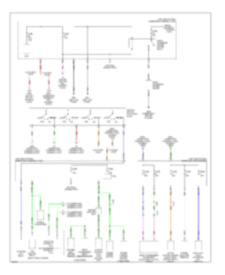
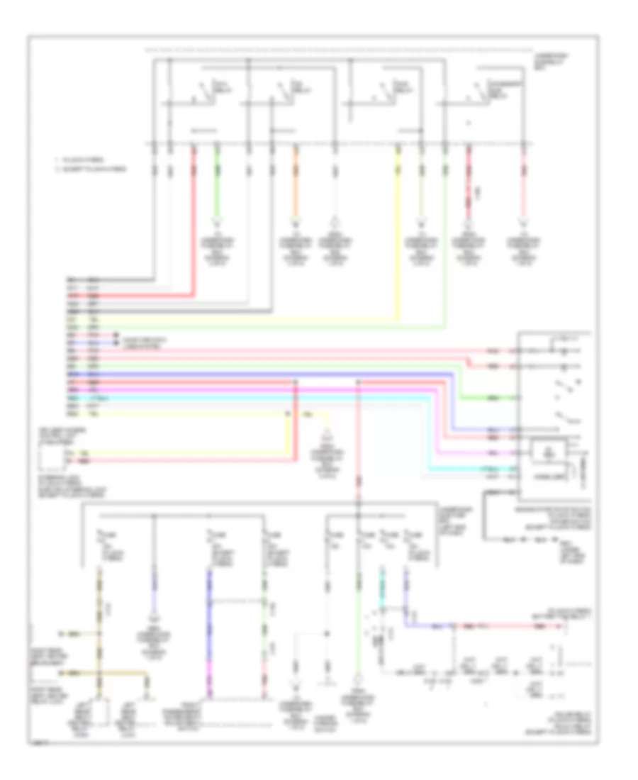
Power Distribution Wiring Diagram, Except Hybrid (5 of 6) for Honda Accord Hybrid Plug-In 2014
List of elements for Power Distribution Wiring Diagram, Except Hybrid (5 of 6) for Honda Accord Hybrid Plug-In 2014:
- (if equipped)
- (left end of dash) under-dash fuse/relay box
- (left end of dash) under-dash sub fuse box
- (optional connector c)
- A/c condenser fan relay (3.5l)
- Acc
- Active control engine mount (acm) control relay (sedan)
- Audio unit/ audio navigation unit (premium)
- C10
- C105
- C110
- C112
- C121
- Center junction box
- Climate control unit/ hvac control unit
- D16
- Diode a (if equipped)
- Driver's seat heater switch
- E20
- Fan control relay
- From fuse 32 (diagram 1 of 6)
- From ignition switch (diagram 5 of 6)
- From under-dash fuse/relay box (diagram 6 of 6)
- From under-dash sub relay box (diagram 6 of 6)
- From under-hood fuse/relay box (diagram 1 of 6)
- Front accessory power socket
- Front accessory power socket relay
- Front passenger's power seat adjustment switch (sedan)
- Front passenger's seat heater switch
- Fuse (a/t) 7.5a
- Fuse 20a
- Fuse 7.5a
- G401 (left kick panel)
- G505 (under right center of dash)
- G601 (left kick panel)
- Ignition switch (w/o start/ stop)
- Lock
- Micu
- Pnk
- Power mirror switch
- Power window master switch (if equipped)
- Radiator fan relay (2.4l)
- Red
- Relay circuit board
- Start
- Starter cut relay
- Stereo amplifier (premium)
- To center junction box (diagram 6 of 6)
- To under-dash fuse/relay box (diagram 4 of 6)
- To under-dash fuse/relay box (diagram 5 of 6)
- To under-hood fuse/relay box (diagram 3 of 6)
- W/ start/ stop
- W/o start/ stop
Power Distribution Wiring Diagram, Except Hybrid (6 of 6) for Honda Accord Hybrid Plug-In 2014
List of elements for Power Distribution Wiring Diagram, Except Hybrid (6 of 6) for Honda Accord Hybrid Plug-In 2014:
- (left end of dash) under-dash fuse/relay box
- (left side of engine compt) under-hood fuse/relay box
- 5v ref
- A24
- Accessory sub relay
- Audio unit/ audio navigation unit
- B12
- B23
- B24
- B25
- B26
- C10
- C102
- C11
- C12
- C22
- C23
- C24
- Center junction box
- Console accessory power socket
- Console accessory power socket relay
- Engine start/stop switch (w/ start/stop)
- From fuse 15 (diagram 1 of 6)
- From under-dash fuse/relay box (diagram 3 of 6)
- From under-dash fuse/relay box (diagram 5 of 6)
- Fuse 10a
- Fuse 12-1 60a
- Fuse 12-3 30a (w/ start /stop) 50a (w/o start /stop)
- Fuse 12-4 30a
- G501 (upper left end of dash)
- G502 (upper left end of dash)
- G503 (under left center of dash)
- Ig1a relay
- Ig1b relay
- Ig2 relay
- Immobilizer
- Keyless access control unit (if equipped)
- Lf ant
- Multi- information display unit
- Navigation switch panel (if equipped)
- Pnk
- Red
- S10
- Steering lock
- To fuse 42 (diagram 1 of 6)
- To ignition switch (diagram 5 of 6)
- To under-dash fuse/relay box (diagram 4 of 6)
- To under-dash fuse/relay box (diagram 5 of 6)
- Under-dash sub relay box
- W/ start/stop
- W/o start/stop
Power Distribution Wiring Diagram, Hybrid (1 of 5) for Honda Accord Hybrid Plug-In 2014
List of elements for Power Distribution Wiring Diagram, Hybrid (1 of 5) for Honda Accord Hybrid Plug-In 2014:
- (left rear of engine compt) under-hood fuse/relay box
- (optional connector)
- 12v battery (except plug-in hybrid) battery (plug-in hybrid)
- A17
- A24
- A35
- Acc unit
- Anc/active sound control unit
- Audio unit/ audio- navigation unit
- B14
- Battery condition monitor module (except plug-in hybrid)
- Brake light relay
- Brake pedal position switch
- C109
- C110
- C12
- C205
- C206
- Center junction box
- Charge lid illumination lamp/ charge indicator (plug-in hybrid)
- Console accessory power socket
- Console accessory power socket relay
- Dc-dc converter
- Driver's junction box
- E23
- Except plug-in hybrid
- From under-dash sub fuse box (diagram 2 of 5)
- From under-dash sub-relay box (diagram 2 of 5)
- Front accessory power socket
- Front accessory power socket relay
- Fuse 10a
- Fuse 12-1 60a
- Fuse 12-10 40a
- Fuse 12-3 60a
- Fuse 12-4 2-4 30a
- Fuse 150a
- Fuse 2-7 30a
- Fuse 20a
- Fuse 3-3 30a
- Fuse 7.5a
- G351 (left rear of engine compt)
- G401 (left kick panel)
- G502 (upper left end of dash)
- G503 (under left center of dash)
- G655 (bottom left front of battery pack assembly)
- G655 (top right front of battery pack assembly)
- G804
- G805
- Gauge control module
- Homelink unit
- J/c c012 (except plug-in hybrid) j/c c007 (plug-in hybrid) (left front of engine compt)
- Junction board (right front of battery pack assembly)
- Keyless access control module (if equipped)
- Keyless access control unit (if equipped)
- M12
- Micu
- Motor control module
- Multi- information display unit
- Navigation switch panel
- Pcm
- Pcu
- Plug-in hybrid
- Pnk
- Power window master switch
- Red
- Sunlight sensor (except plug-in hybrid)
- T10
- T101
- T122
- T57
- T71
- T72
- Telematics control unit (plug-in hybrid)
- To fuse 15 (diagram 4 of 5)
- To fuse 18 (diagram 5 of 5)
- To fuse 2-1 (diagram 5 of 5)
- To fuse 42 (diagram 3 of 5)
- To under-dash sub fuse box (diagram 2 of 5)
- To under-dash sub-relay box (diagram 2 of 5)
- Under- dash fuse/ relay box (left end of dash)
- Vsa modulator control unit
Power Distribution Wiring Diagram, Hybrid (2 of 5) for Honda Accord Hybrid Plug-In 2014
List of elements for Power Distribution Wiring Diagram, Hybrid (2 of 5) for Honda Accord Hybrid Plug-In 2014:
- (plug-in hybrid) battery fan relay 1
- 5v reg
- Accessory sub relay
- B12
- B23
- B24
- B25
- B26
- B28
- C10
- C102
- C11
- C110
- C111
- C112
- C129
- C130
- C131
- C22
- C23
- C24
- C405
- Computer data lines system
- Engine start/stop switch (plug-in hybrid) power switch (except plug-in hybrid)
- Except plug-in hybrid
- From under-dash fuse/relay box (diagram 1 of 5)
- From under-dash fuse/relay box (diagram 3 of 5)
- From under-hood fuse/relay box (diagram 1 of 5)
- Front passenger's power seat adjustment switch
- Fuse 10a
- Fuse 15a
- Fuse 15a (plug-in hybrid)
- Fuse 20a (except plug-in hybrid)
- G501 (upper left end of dash)
- Hazard warning switch
- Ig1a relay
- Ig1b relay
- Ig2 relay
- Ighldb relay (plug-in hybrid) ighld 2 relay (except plug-in hybrid)
- Immobilizer
- Keyless access control unit (if equipped)
- Left rear seat heater relay (high)
- Left rear seat heater relay (low)
- Lf antenna
- Plug-in hybrid
- Pnk
- Red
- Right rear seat heater relay (high)
- Right rear seat heater relay (low)
- Steering lock (plug-in hybrid) electric steering lock (except plug-in hybrid)
- To under-dash fuse/relay box (diagram 1 of 5)
- To under-dash fuse/relay box (diagram 3 of 5)
- To under-dash fuse/relay box (diagram 4 of 5)
- Under-dash sub fuse box (left end of dash)
- Under-dash sub-relay box
Power Distribution Wiring Diagram, Hybrid (3 of 5) for Honda Accord Hybrid Plug-In 2014
List of elements for Power Distribution Wiring Diagram, Hybrid (3 of 5) for Honda Accord Hybrid Plug-In 2014:
- (optional connector)
- A/c compressor
- A/c main relay (plug-in hybrid)
- A38
- Acc unit (touring)
- B19
- Brake light relay
- Brake pedal position switch
- C10
- C105
- C106
- C108
- C109
- C110
- C111
- C112
- C113
- C118
- C122
- C125
- C128
- C129
- C132
- C203
- Center junction box
- Climate control unit
- Control unit (except plug-in hybrid) dr control block (plug-in hybrid)
- Dc-dc converter (except plug-in hybrid)
- Driver's power lumbar support switch
- Driver's seat heater switch
- Driver's unlock relay
- E11
- E19
- E20
- E26
- Electric heater coolant pump relay circuit
- Electric servo brake control unit
- Eps control unit
- Except plug-in hybrid
- F11
- From e under-dash sub-relay box (diagram 2 of 5)
- From j fuse 40 (diagram 1 of 5)
- From under-dash sub-relay box (diagram 2 of 5)
- From under-hood fuse/relay box (diagram 5 of 5)
- Front passenger's power window switch
- Front passenger's seat heater
- Fuse 10a
- Fuse 15a
- Fuse 20a
- Fuse 28-2 10a
- Fuse 7.5a
- J/c c012 (except plug-in hybrid) j/c c007 (plug-in hybrid) (left front of engine compt)
- Left rear seat heater switch
- Lock relay
- Maf/iat sensor
- Micu
- Pcm
- Pgm-fi main relay 2
- Plug-in hybrid
- Pnk
- Power mirror switch
- Power window master switch
- Power window relay
- R14
- Red
- Relay circuit board
- Right rear seat heater switch
- S10
- Secondary ho2s (sensor 2)
- Srs unit
- Steering angle sensor
- Tan
- To keyless access control unit (diagram 2 of 5)
- To relay circuit board (diagram 5 of 5)
- Touring
- Trunk lid actuator relay circuit
- Under-dash fuse/relay box (left end of dash)
- Unlock relay
- Vsa modulator control unit
- Windshield washer main relay
- Windshield wiper high/ low relay
- Windshield wiper intermittent relay
Power Distribution Wiring Diagram, Hybrid (4 of 5) for Honda Accord Hybrid Plug-In 2014
List of elements for Power Distribution Wiring Diagram, Hybrid (4 of 5) for Honda Accord Hybrid Plug-In 2014:
- A10
- A12
- A16
- A17
- A30
- A39
- Acc unit
- Acoustic vehicle alerting control unit
- Anc/ active sound control unit
- Audio unit/ audio- navigation unit (except plug-in hybrid) audio-navigation unit (plug-in hybrid)
- Automatic dimming inside mirror
- B13
- Battery condition monitor module
- C103
- C104
- C108
- C109
- C111
- C115
- C116
- C123
- C125
- C126
- C131
- C132
- C133
- C401
- Can gateway
- Center junction box
- Charge lid illumination lamp/charge indicator relay
- Diode b
- Driver's junction box
- Driver's seat heater relay (high)
- Driver's seat heater relay (low)
- E18
- Except plug-in hybrid
- F17
- Fcw/ldw camera unit
- From m fuse 14 (diagram 1 of 5)
- From under-dash sub-relay box (diagram 2 of 5)
- From under-hood fuse/relay box (diagram 5 of 5)
- Front passenger's air bag cut off indicator
- Front passenger's seat heater relay (high)
- Front passenger's seat heater relay (low)
- Front passenger's weight sensor unit
- Fuel fill door opener switch
- Fuse 10a
- Fuse 18-1 10a (plug-in hybrid)
- Fuse 20a
- Fuse 7.5a
- Gauge control module
- H10
- Head-up warning unit
- Interior light cut relay
- Ldw off switch
- M11
- Micu
- Millimeter wave radar
- Moonroof control unit/ motor
- Plug-in hybrid
- Pnk
- Power seat control unit/ power seat adjustment switch (except plug-in hybrid) power seat control unit (plug-in hybrid)
- Power seat control unit/power seat adjustment switch (except plug-in hybrid) power seat control unit (plug-in hybrid)
- R11
- R13
- Red
- Reverse relay
- Shift lock solenoid
- Srs unit
- Telematics control unit
- Under-dash fuse/relay box (left end of dash)
- W/ acc
Power Distribution Wiring Diagram, Hybrid (5 of 5) for Honda Accord Hybrid Plug-In 2014
List of elements for Power Distribution Wiring Diagram, Hybrid (5 of 5) for Honda Accord Hybrid Plug-In 2014:
- (except plug-in hybrid) headlight relay (plug-in hybrid) headlight low beam relay
- (except plug-in hybrid) ptc heater relay a
- (except plug-in hybrid) ptc heater relay b
- (left rear of engine compt) under-hood fuse/relay box
- (or pnk) red
- A36
- Audio unit/ audio- navigation unit (except plug-in hybrid) audio-navigation unit (plug-in hybrid)
- Auxiliary under-hood fuse/relay box a (left front of engine compt)
- B14
- B20
- Battery fan relay (except plug-in hybrid) battery fan relay 2 (plug-in hybrid)
- Battery sensor
- Blower motor relay
- C112
- C113
- C127
- C129
- C131
- Climate control unit
- Drl relay
- Electric heater coolant pump relay circuit
- Electric motor control module coolant pump relay circuit
- Electric servo brake control unit
- Electric vtc relay
- Engine ewp relay
- Eps control unit
- Etcs control relay
- Except plug-in hybrid
- From fuse 10 (diagram 1 of 5)
- From fuse 21 (diagram 1 of 5)
- From under-dash fuse/relay box (diagram 3 of 5)
- Front fog light relay
- Fuse 10a
- Fuse 12-2 50a
- Fuse 12-5 30a
- Fuse 12-7 14-1 40a
- Fuse 12-9 20a
- Fuse 15a
- Fuse 15a (plug-in hybrid)
- Fuse 2-1 70a
- Fuse 2-2 40a
- Fuse 2-3 20a
- Fuse 2-5 12-6 30a
- Fuse 2-6 40a 30a
- Fuse 20a
- Fuse 20a (except plug-in hybrid)
- Fuse 3-1 30a
- Fuse 3-4 30a
- Fuse 40a
- Fuse 7.5a
- Horn relay
- Ighld 1 relay circuit
- Ignition coil relay
- J/c c007 (except plug-in hybrid) j/c c003 (plug-in hybrid) (right center of dash)
- Multi- information display unit
- Pgm-fi main relay 1
- Pgm-fi sub-relay
- Plug-in hybrid
- Pnk
- Rear window defogger relay
- Red
- Relay circuit board
- Rfc relay
- Stereo amplifier
- Taillight relay
- Telematics control unit
- To under-dash fuse/relay box (diagram 3 of 5)
- To under-dash fuse/relay box (diagram 4 of 5)
- Vsa modulator control unit
- Windshield wiper intermittent relay