POWER DISTRIBUTION
2.4L
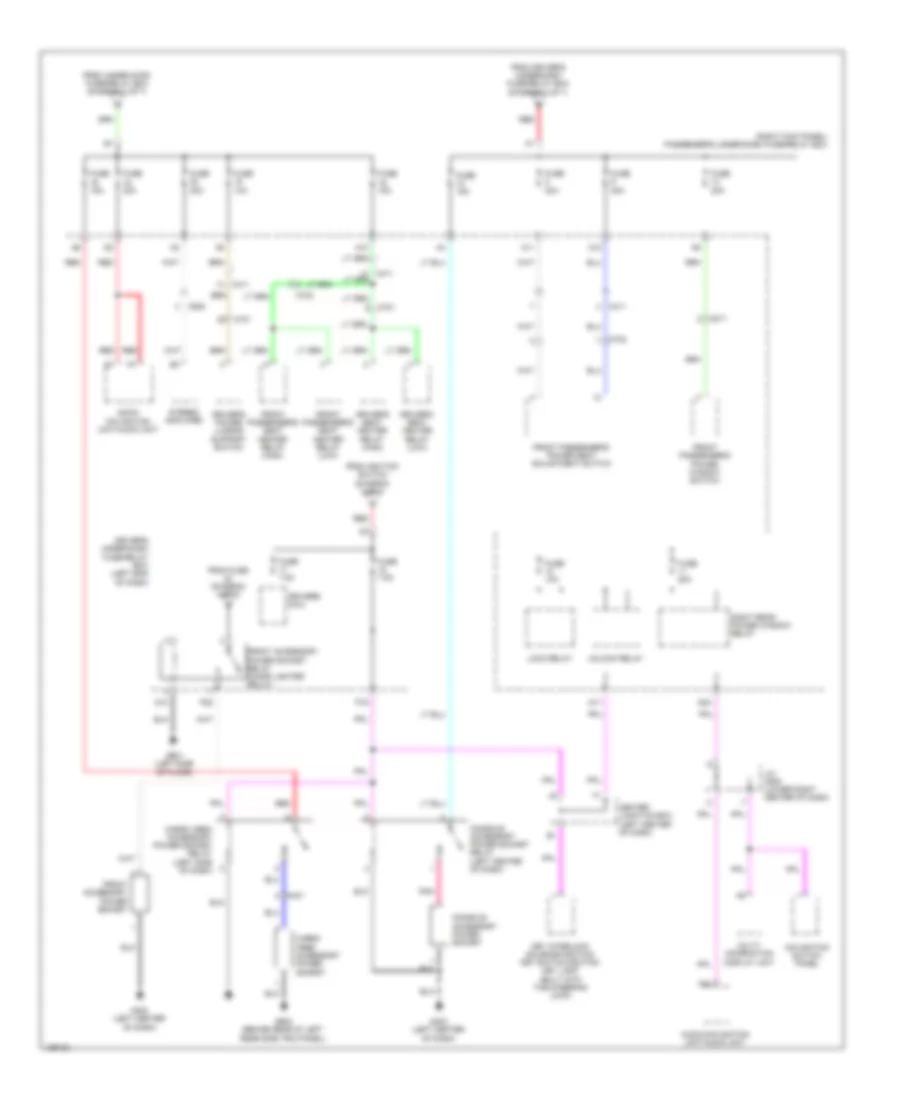
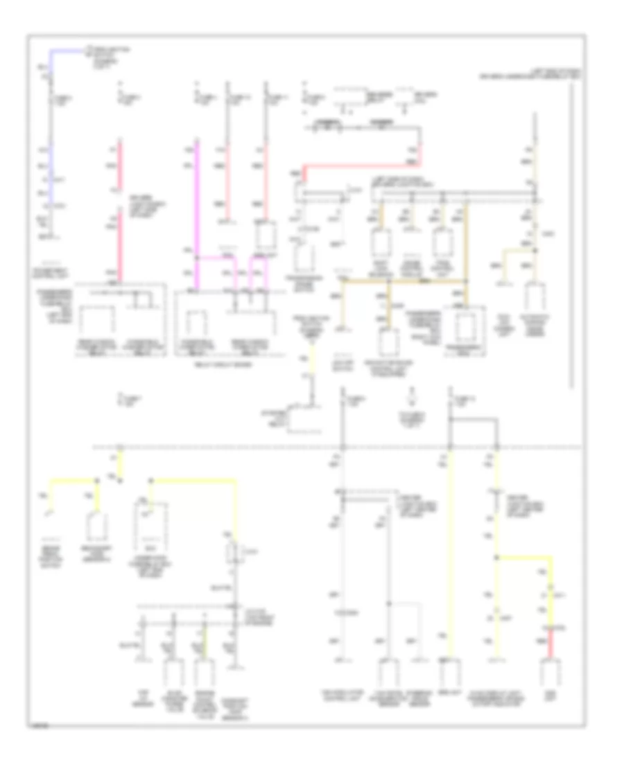
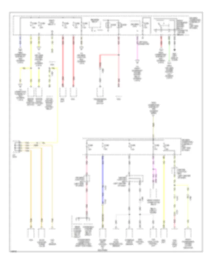
2.4L, Power Distribution Wiring Diagram (1 of 7) for Honda Crosstour EX-L 2014

List of elements for 2.4L, Power Distribution Wiring Diagram (1 of 7) for Honda Crosstour EX-L 2014:
- (diagram 4 of 7)
- (left rear of engine compt) under-hood fuse/relay box
- A/c diode b
- A/f sensor (sensor 1)
- A49
- B13
- Battery
- Brake pedal position switch
- C101
- C201
- C304
- C307
- C407
- Driver's micu
- Driver's under-dash fuse/relay box (left end of dash)
- Driver's under-dash fuse/relay box (left kick panel)
- Evap canister vent shut valve
- F11
- Fuse 1-2 40a
- Fuse 12 15a
- Fuse 15a
- Fuse 2-2 40a
- Fuse 2-3 30a
- Fuse 2-4 40a
- Fuse 4 7.5a
- Fuse 7 15a
- Fuse 8 20a
- G1 (left front of engine compt)
- Hazard warning switch/ front passenger's air bag cut-off indicator
- Horn relay
- Ignition coil relay
- Pcm
- Pgm-fi sub-relay
- Radiator fan relay
- Red
- Relay circuit board
- Starter
- To fuse 1-1
- To passenger's under-dash fuse/relay box (diagram 2 of 7)
- Vsa modulator control unit
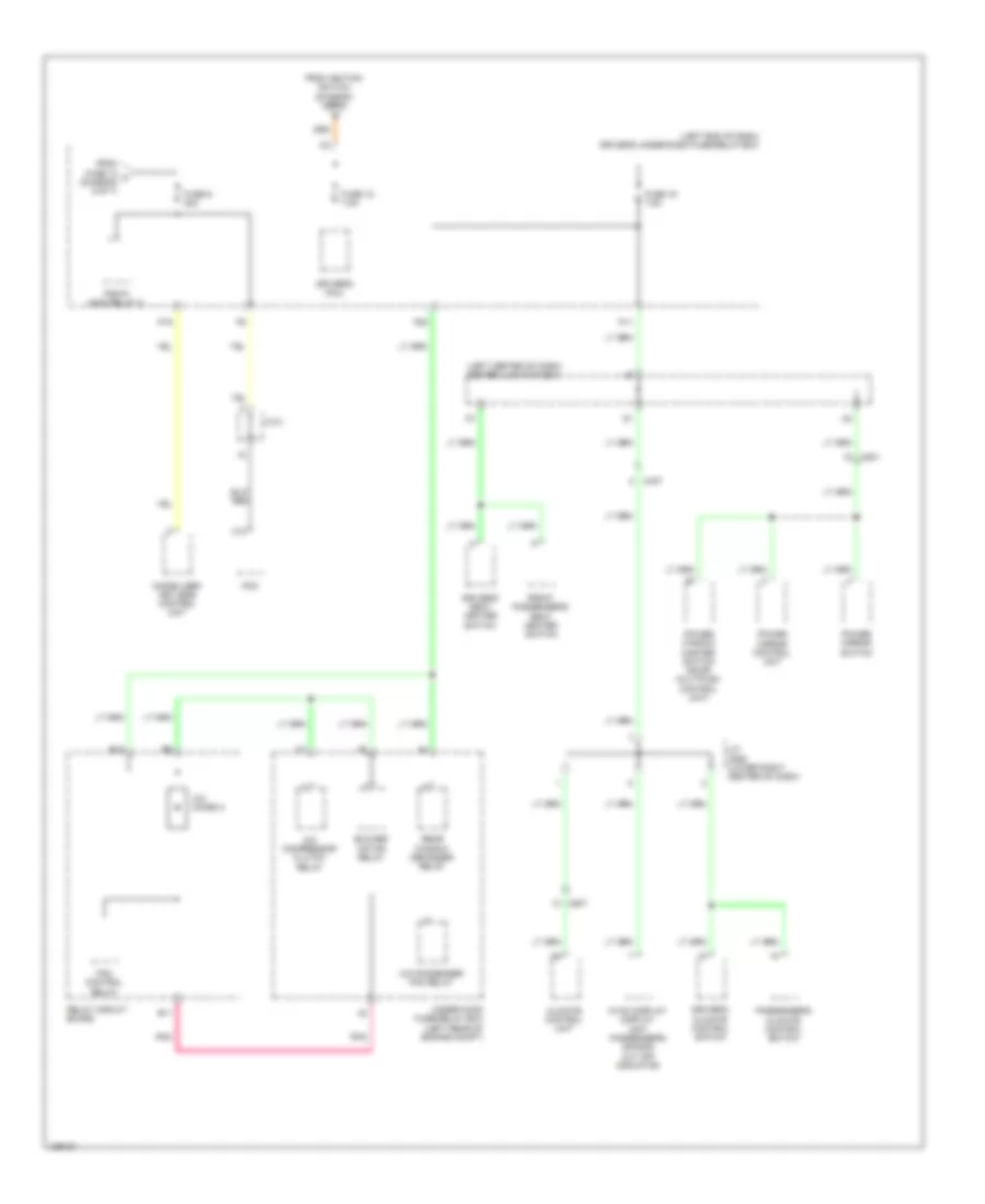
2.4L, Power Distribution Wiring Diagram (2 of 7) for Honda Crosstour EX-L 2014
List of elements for 2.4L, Power Distribution Wiring Diagram (2 of 7) for Honda Crosstour EX-L 2014:
- (right kick panel) passenger's under-dash fuse/relay box
- A10
- A11
- A12
- A17
- A24
- Audio- navigation unit/audio unit
- Audio-navigation unit/audio unit
- C401
- C411
- C508
- C701
- C702
- C811
- Cargo area accessory power socket
- Cargo area accessory power socket relay (left side of dash)
- Center junction box (left center of dash)
- Console accessory power socket
- Console accessory power socket relay (left center of dash)
- D13
- D24
- Driver's micu
- Driver's power lumbar support switch
- Driver's seat heater relay (high)
- Driver's seat heater relay (low)
- Driver's under-dash fuse/relay box (left end of dash)
- From driver's under-dash fuse/relay box (diagram 1 of 7)
- From fuse (diagram 4 of 7)
- From ignition switch (diagram 3 of 7)
- From under-hood fuse/relay box (diagram 1 of 7)
- Front accessory power socket
- Front accessory power socket relay (cigar lighter relay)
- Front passenger's power seat adjustment switch
- Front passenger's power window switch
- Front passenger's seat heater relay (high)
- Front passenger's seat heater relay (low)
- Fuse 10a
- Fuse 15a
- Fuse 20a
- Fuse 7.5a
- G403 (left center of dash)
- G601 (left side of floor)
- G603 (behind rear of left rear side trim panel)
- J/c c505 (lower right center of dash)
- Key interlock solenoid/ignition key switch/ignition key light (built into the steering lock)
- Lock relay
- Multi- information display unit
- Navigation switch panel
- P16
- P20
- Pnk
- Red
- Right rear power window relay
- Stereo amplifier
- Unlock relay
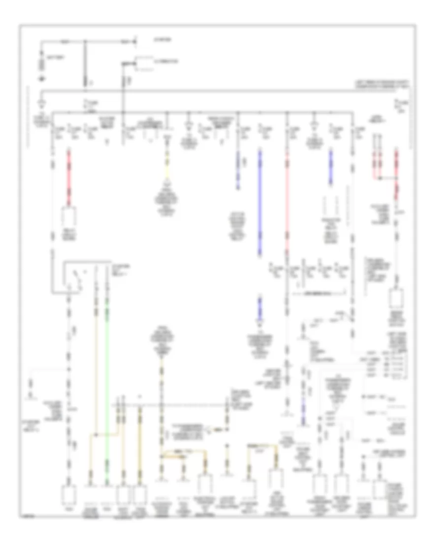
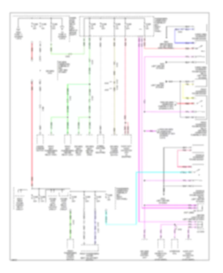
2.4L, Power Distribution Wiring Diagram (3 of 7) for Honda Crosstour EX-L 2014
List of elements for 2.4L, Power Distribution Wiring Diagram (3 of 7) for Honda Crosstour EX-L 2014:
- (left rear of engine compt) under-hood fuse/relay box
- (left side of dash) driver's junction box
- (right kick panel) passenger's under-dash fuse/relay box
- A/c compressor clutch relay
- A18
- Acc
- Alternator
- Anc/active sound control unit
- B12
- B14
- B25
- Blower motor relay
- C403
- C411
- C701
- C801
- C811
- D26
- Dlc
- Driver's door courtesy light
- Driver's micu
- Driver's under-dash fuse/relay box (left end of dash)
- E17
- E18
- Eld
- Etcs control relay
- F16
- Fcw/ldw camera unit
- From driver's under-dash fuse/relay box (diagram 4 of 7)
- From fuse 3-7 (diagram 4 of 7)
- Front passenger's door courtesy light
- Fuse 10a
- Fuse 15a
- Fuse 2 10a
- Fuse 3 10a
- Fuse 40a
- Fuse 6 7.5a
- Fuse 7.5a
- G10
- Gauge control module
- H14
- Ignition switch
- Immobilizer keyless control unit
- J/c c506 (lower right center of dash)
- Keyless access control unit
- Lock
- Multi- information display unit
- Navigation unit
- Passenger's micu
- Pgm-fi main relay 1
- Power mirror control unit
- Power seat control unit (w/ memory)
- Power window master switch (door multiplex control unit)
- Rear window defogger relay
- Red
- Right fog light (if equipped)
- Right front side marker light
- Right front turn signal/ parking light
- Right headlight (high)
- Right headlight (low)
- Start
- T102
- To driver's under-dash fuse/relay box (diagram 2 of 7)
- To driver's under-dash fuse/relay box (diagram 5 of 7)
- To driver's under-dash fuse/relay box (diagram 6 of 7)
- To driver's under-dash fuse/relay box (diagram 7 of 7)
- To passenger's under- dash fuse/ relay box diagram 5 of 7)
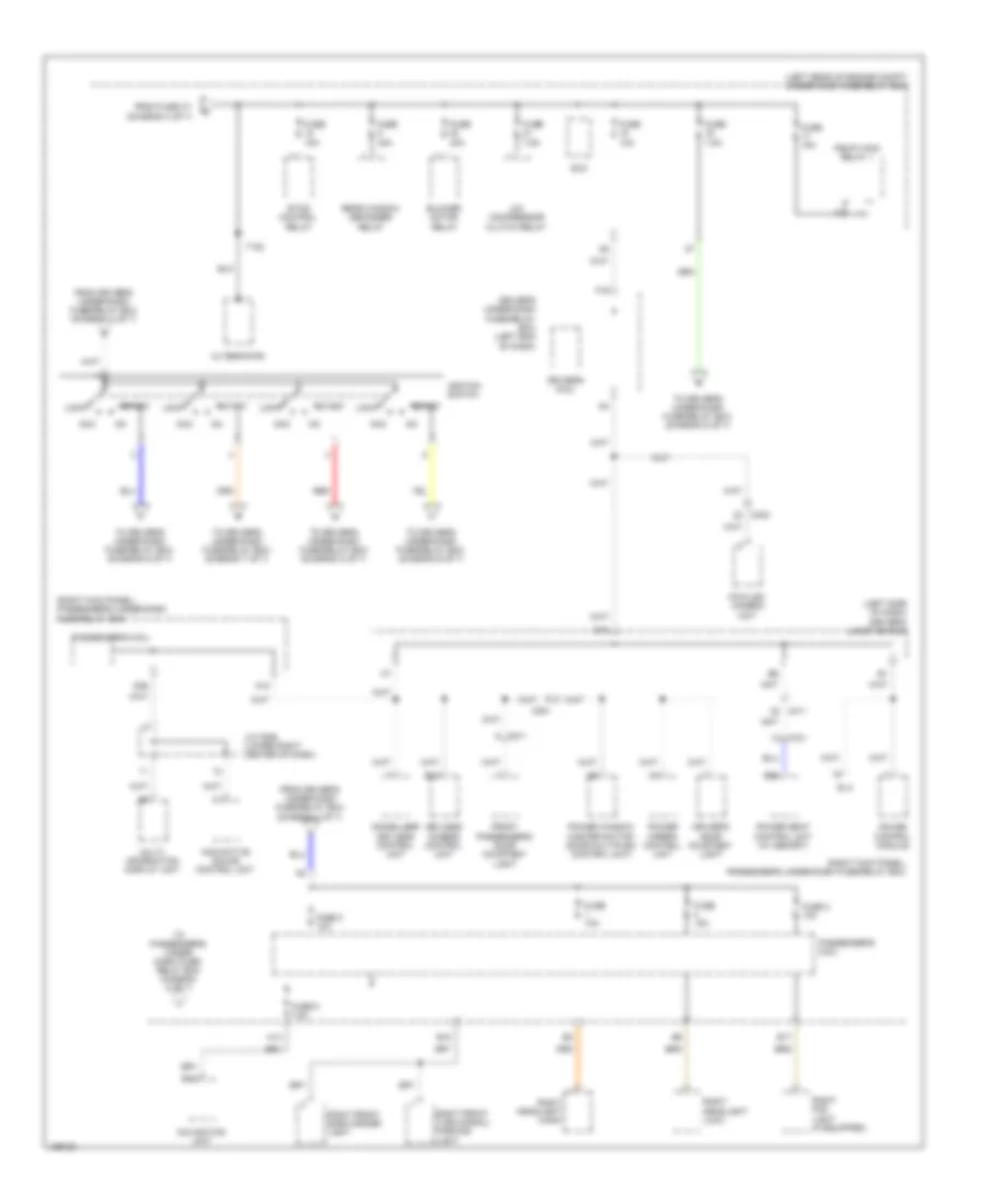
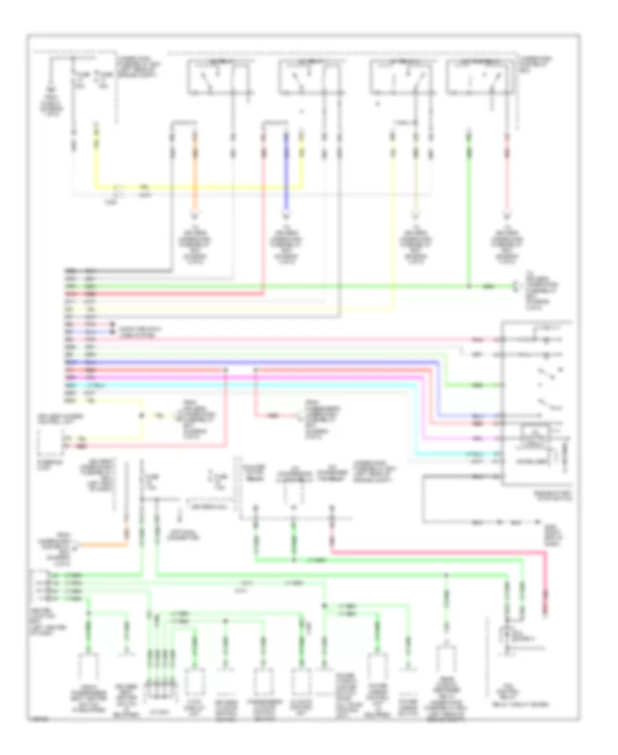
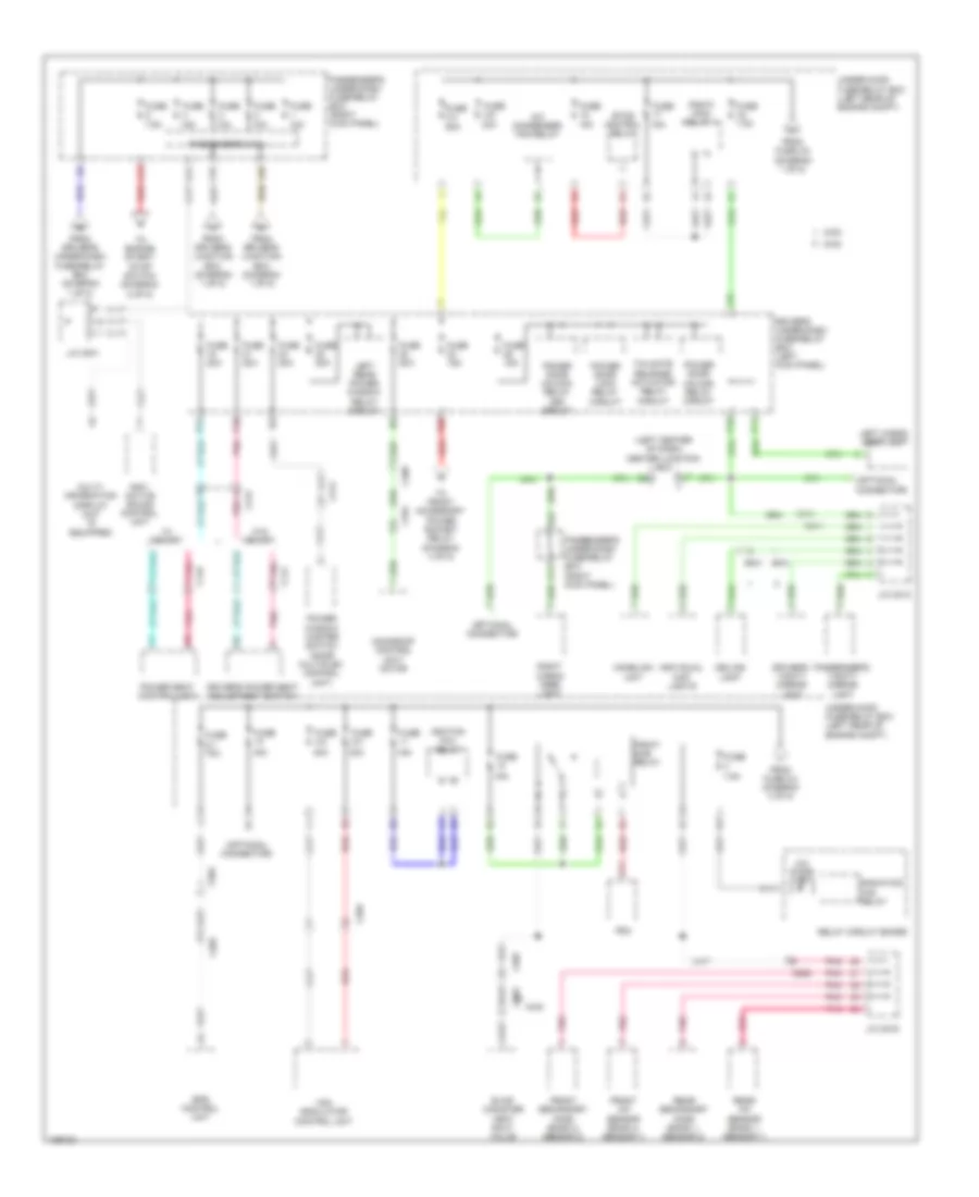
2.4L, Power Distribution Wiring Diagram (4 of 7) for Honda Crosstour EX-L 2014
List of elements for 2.4L, Power Distribution Wiring Diagram (4 of 7) for Honda Crosstour EX-L 2014:
- (left kick panel) driver's under-dash fuse/relay box
- (left rear of engine compt) under-hood fuse/relay box
- A/c condenser fan relay
- C404
- C411
- C452
- C701
- C801
- Center junction box (left center of dash)
- Driver's micu
- From fuse 1-2 (diagram 1 of 7)
- Fuse 1-1 100a
- Fuse 15a
- Fuse 20a
- Fuse 26 10a
- Fuse 27 10a
- Fuse 28 10a
- Fuse 29 7.5a
- Fuse 3-1 50a
- Fuse 3-3 30a
- Fuse 3-4 60a
- Fuse 3-5 30a
- Fuse 3-6 30a
- Fuse 3-7 30a
- Fuse 30 15a
- Left rear power window relay
- Lock relay
- Moonroof control unit/ motor
- N13
- P17
- P18
- Pnk
- Power seat control unit
- Power window master switch (door multiplex control unit)
- Radiator control relay
- Red
- Relay circuit board
- Tailgate actuator relay
- To front accessory power socket relay (cigar lighter relay) (diagram 2 of 7)
- To fuse 18 (diagram 3 of 7)
- To ignition switch (diagram 3 of 7)
- To passenger's under-dash fuse/relay box (diagram 3 of 7)
- Tpms control unit
- Unlock relay
- Windshield wiper motor relay
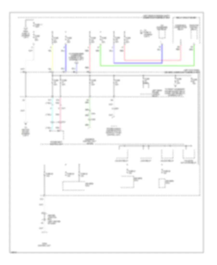
2.4L, Power Distribution Wiring Diagram (5 of 7) for Honda Crosstour EX-L 2014
List of elements for 2.4L, Power Distribution Wiring Diagram (5 of 7) for Honda Crosstour EX-L 2014:
- (left center of dash) center junction box
- (left end of dash) driver's under-dash fuse/relay box
- (left front of roof) j/c c451
- (optional connector)
- (right kick panel) passenger's under-dash fuse/relay box
- A/t gear position indicator panel light/park pin switch
- A10
- A19
- A22
- Audio remote switch
- C403
- C452
- Cable reel (top of steering column)
- Ceiling light
- Center junction box (left center of dash)
- D11
- D14
- Driver's climate control switch
- Driver's seat heater switch
- Driver's vanity mirror light
- F26
- From fuse 6 m (diagram 3 of 7)
- From under-hood fuse/relay box (diagram 3 of 7)
- Front passenger's seat heater switch
- Glove box light
- H13
- Hazard warning switch
- Hvac display unit/passenger's air bag cutoff indicator
- Individual map lights
- Interior light switch (moonroof switch)
- J/c c505 (lower right center of dash)
- Key interlock solenoid/ ignition key switch/ignition key light (built into the steering lock)
- Ldw off switch
- Left cargo area light
- Navigation switch panel
- P10
- Passenger's climate control switch
- Passenger's under-dash fuse/relay box (right kick panel)
- Passenger's vanity mirror light
- Right cargo area light
- Steering wheel
- Vsa off switch
2.4L, Power Distribution Wiring Diagram (6 of 7) for Honda Crosstour EX-L 2014
List of elements for 2.4L, Power Distribution Wiring Diagram (6 of 7) for Honda Crosstour EX-L 2014:
- (left end of dash) driver's under-dash fuse/relay box
- (left side of dash) driver's junction box
- A22
- A23
- A28
- A32
- Anc/active sound control unit (if equipped)
- Automatic dimming inside mirror
- B25
- B27
- Brake pedal position switch
- C101
- C106
- C202
- C403
- C407
- C409
- C411
- C701
- C702
- Camshaft position (cmp) sensor a
- Center junction box (left center of dash)
- D10
- Diode d
- Diode e
- Driver's junction box (left side of dash)
- Driver's micu
- Eld
- Engine mount control solenoid valve
- Evap canister purge valve
- F15
- F25
- F28
- Fcw/ ldw camera unit
- From ignition switch (diagram 3 of 7)
- Fuse 10 10a
- Fuse 11 10a
- Fuse 12 7.5a
- Fuse 2 7.5a
- Fuse 3 15a
- Fuse 4 10a
- Fuse 5 7.5a
- Fuse 6 7.5a
- Fuse 7 15a
- Gauge control module
- Hvac display unit/ passenger's air bag cutoff indicator
- J/c c103 (top front of engine)
- Ldw off switch
- Maf iat sensor
- N12
- Ods unit
- Passenger's micu
- Passenger's under-dash fuse/relay box (left end of dash)
- Passenger's under-dash fuse/relay box (right kick panel)
- Pcm
- Pnk
- Power seat control unit
- Rear window washer motor relay
- Rear window wiper motor relay
- Red
- Relay circuit board
- Reverse relay
- Secondary ho2s (sensor 2)
- Shift lock solenoid
- Srs unit
- Starter cut relay
- Steering angle sensor
- To fuse 9 (diagram 7 of 7)
- Tpms control unit
- Transmission range switch
- Under-hood fuse/relay box (left end of dash)
- Vsa modulator control unit
- Windshield washer motor relay
- Windshield wiper motor relay
- Yaw rate- acceleration sensor
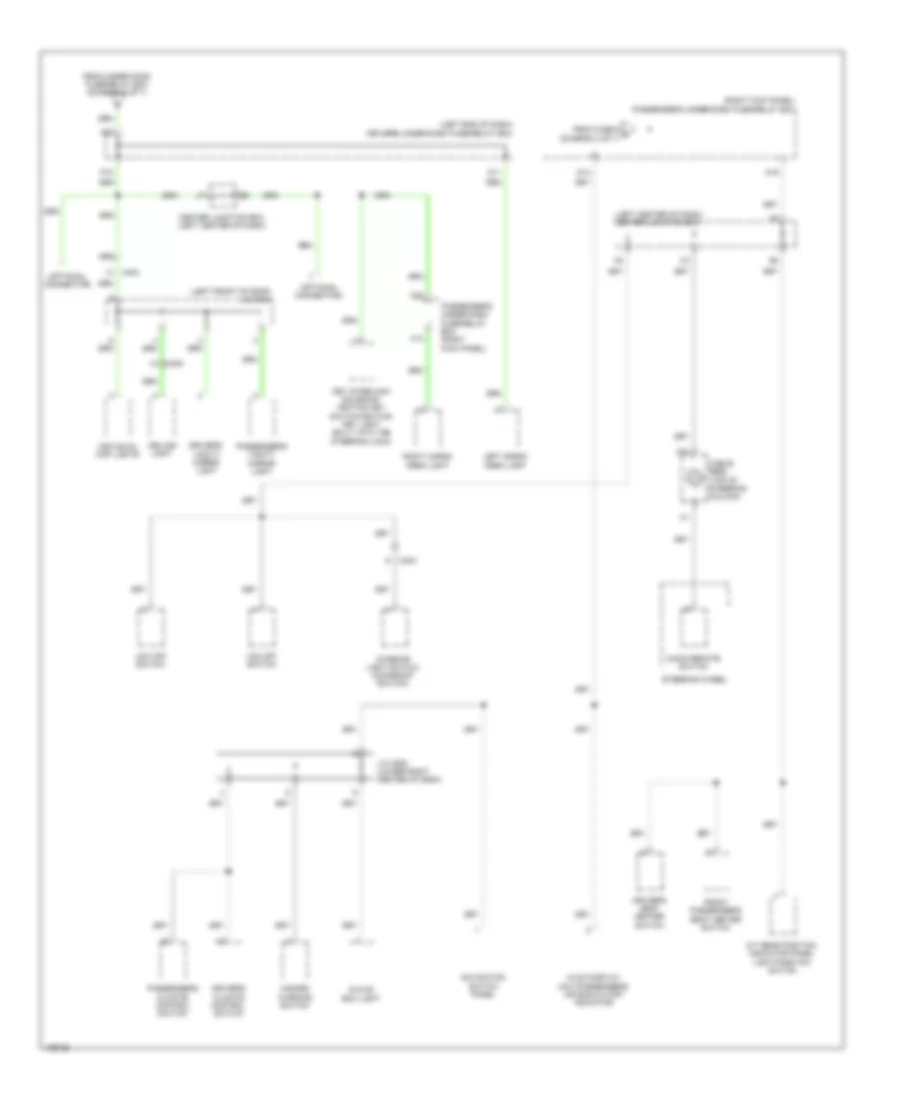
2.4L, Power Distribution Wiring Diagram (7 of 7) for Honda Crosstour EX-L 2014
List of elements for 2.4L, Power Distribution Wiring Diagram (7 of 7) for Honda Crosstour EX-L 2014:
- (left center of dash) center junction box
- (left end of dash) driver's under-dash fuse/relay box
- A/c compressor clutch relay
- A/c condenser fan relay
- A/c diode a
- B11
- B12
- Blower motor relay
- C10
- C101
- C407
- C507
- C801
- Climate control unit
- Driver's climate control switch
- Driver's micu
- Driver's seat heater switch
- F29
- Fan control relay
- From fuse 12 (diagram 6 of 7)
- From ignition switch (diagram 3 of 7)
- Front passenger's seat heater switch
- Fuse 15 7.5a
- Fuse 16 7.5a
- Fuse 9 20a
- Hvac display display unit/ passenger's air bag cut off indicator
- Immobilizer keyless control unit
- J/c c506 (lower right center of dash)
- P11
- P19
- Passenger's climate control switch
- Pcm
- Pgm-fi main relay 2
- Pnk
- Power mirror control unit
- Power mirror switch
- Power window master switch (door multiplex control unit)
- Rear window defogger relay
- Relay circuit board
- Under-hood fuse/relay box (left rear of engine compt)
3.5L
3.5L, Power Distribution Wiring Diagram (1 of 5) for Honda Crosstour EX-L 2014
List of elements for 3.5L, Power Distribution Wiring Diagram (1 of 5) for Honda Crosstour EX-L 2014:
- (left rear of engine compt) under-hood fuse/relay box
- (left side of dash) driver's junction box
- (not used)
- 120a
- 20a
- 4wd
- A/c compressor clutch relay
- A26
- Active control engine mount (acm) control relay
- Alternator
- Anc/ active sound control unit (if equipped)
- Automatic dimming inside mirror
- Auxiliary under-
- B14
- B25
- Battery
- Blower motor relay
- Brake pedal position switch
- C107
- C142
- C403
- C408
- C411
- C412
- C413
- C414
- C701
- Center junction box (left center of dash)
- Dash fuse holder a
- Dash fuse holder b
- Dlc
- Driver's door courtesy light
- Driver's junction box (left side of dash)
- Driver's micu
- Driver's under-dash fuse/relay box (left end of dash)
- Eld
- Electrical compass unit (if equipped)
- F16
- F24
- Fcw/ ldw camera unit
- Fcw/ ldw camera unit (if equipped)
- From driver's under-dash fuse/relay box (diagram 3 of 5)
- Front passenger's door courtesy light
- Fuse
- Fuse 1-1
- Fuse 10a
- Fuse 15a
- Fuse 20a
- Fuse 3-1 50a
- Fuse 3-3 30a
- Fuse 3-5 30a
- Fuse 3-6 30a
- Fuse 3-7 20a
- Fuse 40a
- Fuse 7.5a
- G10
- Gauge control module
- Horn relay
- Keyless access control unit
- Lwd off switch (if equipped)
- N/a
- N11
- N13
- Passenger's under-dash fuse/relay box (diagram 5 of 5)
- Pcm
- Power mirror control unit
- Power seat control unit (if equipped)
- Power window master switch (door multiplex control unit)
- Radiator fan relay
- Rear window defogger relay
- Red
- Relay circuit board
- Shift lock solenoid
- Starter
- Starter cut relay 1
- Starter cut relay 2
- T102
- To fuse 1-2 (diagram 4 of 5)
- To fuse 14 (diagram 2 of 5)
- To fuse 16 (diagram 5 of 5)
- To passenger's under-dash fuse/relay box (diagram 5 of 5)
- Tpms control unit
3.5L, Power Distribution Wiring Diagram (2 of 5) for Honda Crosstour EX-L 2014
List of elements for 3.5L, Power Distribution Wiring Diagram (2 of 5) for Honda Crosstour EX-L 2014:
- (optional connector)
- 30a
- 5v control circuit
- A/c compressor clutch relay
- A/c condenser fan relay
- A/c diode a
- Acc sub relay
- B11
- B12
- B23
- B24
- B25
- B26
- B28
- Blower motor relay
- C10
- C103
- C106
- C11
- C22
- C23
- C24
- C402
- C414
- Center junction box (left center of dash)
- Climate control unit
- Computer data lines system
- Driver's climate control switch
- Driver's micu
- Driver's seat heater switch (if equipped)
- Driver's under-dash fuse/relay box (left end of dash)
- Engine start/ stop switch
- F29
- Fan control relay
- From driver's under-dash fuse/relay box (diagram 3 of 5)
- From fuse 21 (diagram 1 of 5)
- From passenger's under-dash fuse/relay box (diagram 5 of 5)
- From under-dash sub relay s box (diagram 2 of 5)
- Front passenger's seat heater switch (if equipped)
- Fuse
- Fuse 7.5a
- G405 (right end of dash)
- Hvac display unit
- Ig1 relay 1
- Ig1 relay 2
- Ig2 relay
- Immobilizer
- J/c c001
- Keyless access control unit
- Lf antenna
- P11
- Passenger's climate control switch
- Pnk
- Power mirror control unit (if equipped)
- Power mirror switch
- Power window master switch (door multiplex control unit)
- Rear window defogger relay
- Red
- Relay circuit board
- Steering lock
- To driver's under-dash fuse/relay box (diagram 2 of 5)
- To driver's under-dash fuse/relay box (diagram 3 of 5)
- Under-dash sub relay box
- Under-hood fuse/relay box (left rear of engine compt)
3.5L, Power Distribution Wiring Diagram (3 of 5) for Honda Crosstour EX-L 2014
List of elements for 3.5L, Power Distribution Wiring Diagram (3 of 5) for Honda Crosstour EX-L 2014:
- (optional connector)
- 10a
- 15a
- 20a
- 7.5a
- A16
- A18
- A32
- A38
- A39
- Active control engine mount control relay
- B27
- Brake pedal position switch
- C106
- C131
- C142
- C205
- C403
- C412
- C506
- Center junction box (left center of dash)
- D10
- D13
- D27
- Diode c
- Diode d
- Driver's junction box (left side of dash)
- Driver's micu
- Driver's under-dash fuse/relay box (left end of dash)
- Engine mount control unit
- Eps control unit
- Evap canister purge valve
- F15
- F25
- F28
- From keyless access control unit (diagram 2 of 5)
- From under-dash sub relay box (diagram 2 of 5)
- Front accessory power socket relay (cigarette lighter relay)
- Front passenger's air bag cutoff indicator
- Fuse
- Fuse 10a
- Fuse 15a
- Fuse 7.5a
- G601 (left side of floor)
- J/c c015
- Maf iat sensor
- N10
- N12
- Ods unit/ opds unit
- P16
- P19
- Passenger's under-dash fuse/relay box (right kick panel)
- Pcm
- Pgm-fi main relay 2
- Pnk
- Power seat control unit (if equipped)
- Rear window washer motor relay circuit
- Rear window wiper motor relay
- Red
- Relay circuit board
- Reverse relay
- Srs unit
- Steering angle sensor
- Tan
- To driver's junction box (diagram 1 of 5)
- To front accessory power socket relay (diagram 4 of 5)
- To keyless access control unit (diagram 2 of 5)
- To under-hood fuse/relay box (diagram 1 of 5)
- Transmission range switch
- Vsa modulator control unit
- Windshield washer motor relay circuit
- Yaw rate- acceleration sensor
3.5L, Power Distribution Wiring Diagram (4 of 5) for Honda Crosstour EX-L 2014
List of elements for 3.5L, Power Distribution Wiring Diagram (4 of 5) for Honda Crosstour EX-L 2014:
- (not used)
- 10a
- 15a
- 20a
- 2wd
- 40a
- 4wd
- A10
- A11
- A12
- A17
- A24
- Audio unit/ audio navigation unit (if equipped)
- Audio unit/ audio- navigation unit (if equipped)
- C106
- C12
- C131
- C141
- C142
- C402
- C404
- C412
- C413
- Cargo area accessory power socket
- Cargo area accessory power socket relay (left side of dash)
- Center junction box (left center of dash)
- Console accessory power socket
- Console accessory power socket relay (left center of dash)
- D24
- Driver's micu
- Driver's power lumbar support switch
- Driver's seat heater relay (high)
- Driver's seat heater relay (low)
- Driver's under-dash fuse/relay box (left end of dash)
- F11
- From driver's under-dash fuse/relay box (diagram 3 of 5)
- From driver's under-dash q fuse/relay box (diagram 5 of 5)
- From fuse 1-1 (diagram 1 of 5)
- Front accessory power socket
- Front accessory power socket relay (driver's under-dash fuse/relay box)
- Front passenger's power seat adjustment switch
- Front passenger's power window switch
- Front seat passenger's heater relay (high)
- Front seat passenger's heater relay (low)
- Fuse
- Fuse 1-2
- Fuse 10a
- Fuse 2-4
- Fuse 20a
- G403 (left center of dash)
- G603 (behind rear of left rear side trim panel)
- Hazard warning switch
- Interface dial
- J/c c002
- Keyless access control unit
- Multi- information display unit (if equipped)
- Passenger's under-dash fuse/relay box (right kick panel)
- Pnk
- Power door lock relay (lock) circuit
- Power door lock relay (unlock) circuit
- Red
- Right rear power window relay circuit
- Stereo amplifier (if equipped)
- To fuse 12 (diagram 5 of 5)
- Under- hood fuse/ relay box (left rear of engine compt)
3.5L, Power Distribution Wiring Diagram (5 of 5) for Honda Crosstour EX-L 2014
List of elements for 3.5L, Power Distribution Wiring Diagram (5 of 5) for Honda Crosstour EX-L 2014:
- (left center of dash) center junction box
- (optional connector)
- 10a
- 15a
- 2wd
- 30a
- 40a
- 4wd
- 7.5a
- A/c condenser fan relay
- A/c diode b
- A14
- A16
- A18
- A22
- A28
- Anc/ active sound control unit
- B13
- C141
- C142
- C203
- C204
- C409
- C411
- C412
- C414
- C504
- C506
- C507
- C603
- C701
- Ceiling light
- D11
- D26
- Driver's power seat adjustment switch
- Driver's under-dash fuse/relay box (left kick panel)
- Driver's vanity mirror light
- Eps control unit
- Etcs control relay
- Evap canister vent shut valve
- F26
- From driver's junction box (diagram 1 of 5)
- From driver's under-dash fuse/relay box (diagram 1 of 5)
- From fuse 2-4 (diagram 4 of 5)
- From fuse 3-5 (diagram 1 of 5)
- Front a/f sensor (bank 2, sensor 1)
- Front secondary ho2s (bank 2, sensor 2)
- Fuse
- Fuse 15a
- Fuse 2-1 70a
- Fuse 2-2
- Fuse 2-3
- Fuse 20a
- Fuse 3-4 60a
- Fuse 3-8
- Fuse 7.5a
- Homelink unit
- Ignition coil relay
- Individual map lights
- J/c c001
- J/c c012
- J/c c016
- Left cargo area light
- Left rear power window relay circuit
- Moonroof control unit/ motor
- Multi- information display unit (if equipped)
- P10
- P17
- P18
- P20
- Passenger's micu
- Passenger's under-dash fuse/relay box (right kick panel)
- Passenger's vanity mirror light
- Pcm
- Pgm-fi main relay 1
- Pgm-fi sub relay
- Pnk
- Power door lock relay circuit
- Power door unlock relay (dr) circuit
- Power door unlock relay circuit
- Power seat control unit
- Power window master switch (door multiplex control unit)
- Radiation fan relay
- Rear a/f sensor (bank 1, sensor 1)
- Rear secondary ho2s (bank 1, sensor 2)
- Red
- Relay circuit board
- Right cargo area light
- Tailgate release actuator relay circuit
- To engine start/ stop switch (diagram 2 of 5)
- To front accessory power socket relay (diagram 4 of 5)
- Under-hood fuse/relay box (left rear of engine compt)
- Vsa modulator control unit
- W/ memory
- W/o memory