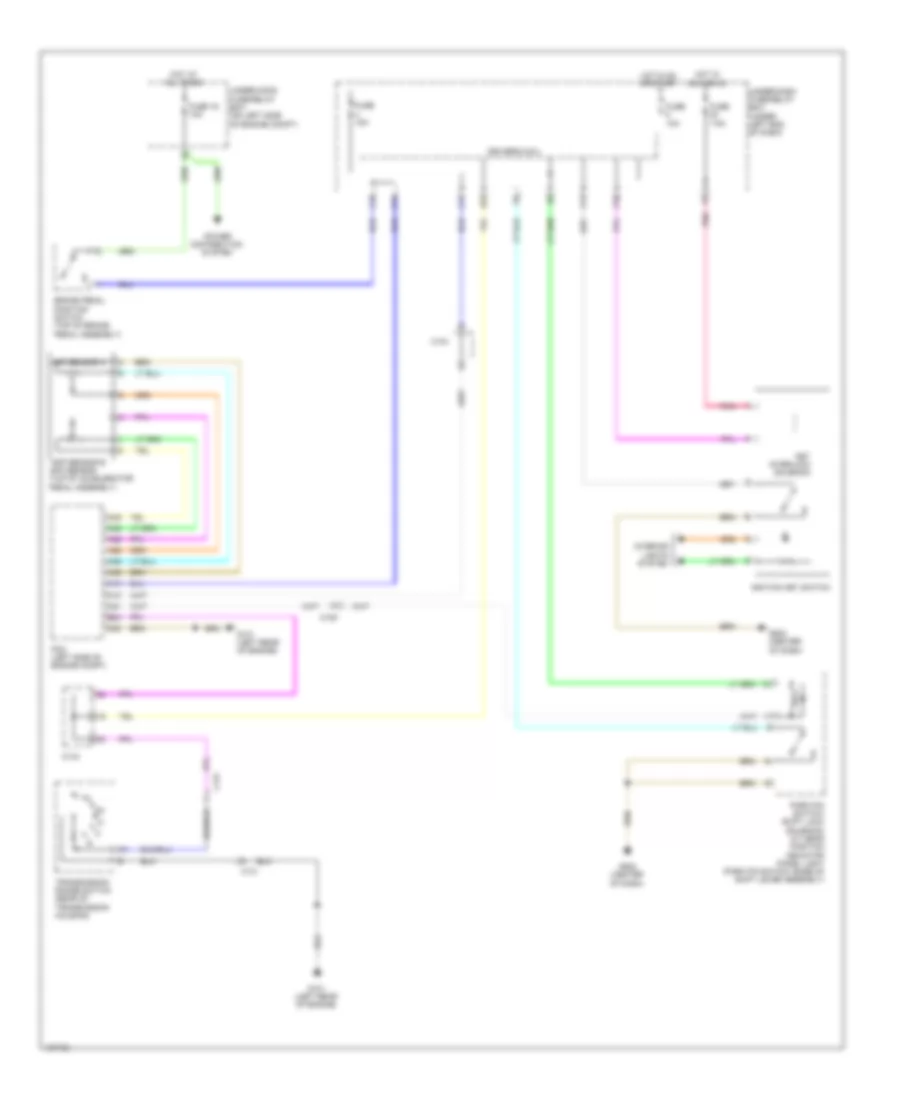
SHIFT INTERLOCK
Shift Interlock Wiring Diagram for Honda CR-V EX-L 2014
List of elements for Shift Interlock Wiring Diagram for Honda CR-V EX-L 2014:
- A13
- A21
- A28
- A29
- A35
- A36
- A45
- A46
- App sensor a
- App sensor b app sensor (top of accelerator pedal assembly)
- B24
- Brake pedal position switch (top of brake pedal assembly)
- C10
- C105
- C13
- C131
- C134
- C16
- C20
- D11
- D22
- Driver's micu
- Fuse 10a
- Fuse 15a
- Fuse 16 10a
- Fuse 7.5a
- G101 (left rear of engine)
- G502 (center of dash)
- Hot at all times
- Hot in acc or on
- Hot in on or start
- Ignition key switch
- Interior lights system
- Key interlock solenoid
- P10
- P11
- Park pin switch/ shift lock solenoid/ a/t gear position indicator panel light (park pin switch: base of shift lever assembly)
- Pcm (left side of engine compt)
- Pnk
- Power distribution system
- Transmission range switch (rear of transmission housing)
- Under-dash fuse/relay box (under left end of dash)
- Under-hood fuse/relay box (on left side of engine compt)
 English