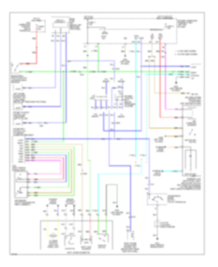
SHIFT INTERLOCK
Shift Interlock Wiring Diagram for Honda Odyssey LX 2014
List of elements for Shift Interlock Wiring Diagram for Honda Odyssey LX 2014:
- 20a
- A/t gear position indicator panel light
- A15
- A16
- A17
- A18
- A19
- A24
- A25
- A26
- A27
- App sensor (top of accelerator pedal assembly)
- Apsa
- Apsb
- Atpp
- B11
- B19
- B35
- Bksw
- Brake pedal position switch (on brake pedal bracket)
- C10
- C101
- C205
- C212
- C304
- C404
- C415
- C601
- D4 switch
- Driver's junction box 2 (behind instrument cluster)
- Driver's micu
- Driver's under-dash fuse/relay box (left end of dash)
- Engine controls system
- Fuel fill door relay
- Fuse 11 7.5a
- Fuse 13 7.5a
- Fuse 9
- G101 (right rear of engine compt)
- G402 (left side of dash)
- G403 (left center of dash)
- Hot at all times
- Hot in on or start
- Hot w/ acc cut relay energized
- Ig 1 meter
- Ig key sw
- Ignition key light
- Ignition key switch
- Interior lights system
- J/c c102 (top right side of engine)
- J/c c407
- Key interlock solenoid
- Key lock sol-
- Key sw
- Keyless access control unit (if equipped) (left center of dash)
- Left power sliding door control unit (if equipped) (behind left rear side trim panel)
- Lg1
- Main under-hood fuse box (above transaxle)
- Memory
- P-pin sw
- Park pin switch
- Pcm (right side of engine compt)
- Pg1
- Power seat control unit (w/ memory) (under driver's seat)
- Power tailgate control unit (if equipped) (left "d" pillar)
- Q17
- Q18
- Q19
- Rear fuse box (behind left rear side trim panel)
- Red
- Right power sliding door control unit (behind right rear side trim panel)
- Sg3
- Sg4
- Shift lever connector
- Shift lock solenoid
- Sls
- Steering lock (ignition key light/ ignition key switch/ key interlock solenoid) (w/o keyless access) (right side of steering column)
- Stop sw
- Transmission range switch (top of transaxle)
- Vcc3
- Vcc4
- W/ keyless access
- W/o
- W/o keyless access
 English