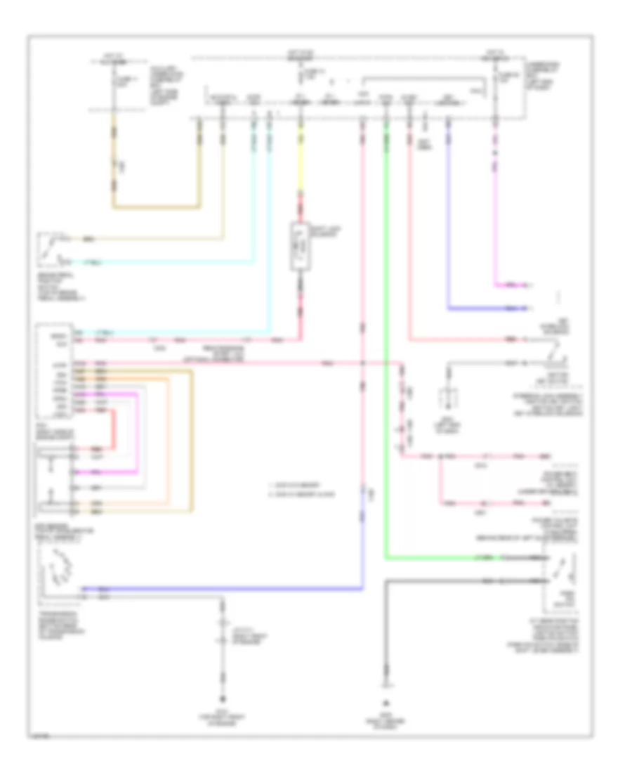
SHIFT INTERLOCK
Shift Interlock Wiring Diagram for Honda Pilot EX-L 2014
List of elements for Shift Interlock Wiring Diagram for Honda Pilot EX-L 2014:
- (not used)
- +b stop & horn
- 2wd w/ memory & 4wd
- 2wd w/o memory
- A/t gear position indicator panel light/d3 switch/ park pin switch (park pin switch: base of shift lever assembly)
- A16
- A18
- A19
- A24
- A25
- A26
- A27
- Acc
- App sensor (top of accelerator pedal assembly)
- Apsa
- Apsb
- Atp-p
- Atpp
- Auxiliary under-hood fuse/relay box (left side of engine compt)
- B26
- Bksw
- Brake pedal position switch (top of brake pedal assembly)
- C102
- C201
- C303
- C402
- C501
- C512
- F25
- F27
- F30
- F31
- Fuse 10 7.5a
- Fuse 11 20a
- Fuse 35 10a
- G101 (top right front of engine)
- G16
- G401 (left end of dash)
- G403 (right center of dash)
- Hot at all times
- Hot in acc or on
- Hot in on or start
- Ig 1 meter
- Ig key sw
- Ignition key switch
- J/c c111 (right front of engine)
- Key interlock solenoid
- Key lock sol
- Micu
- Nca
- P-pin sw
- Park pin switch
- Pcm (right side of engine compt)
- Pnk
- Power seat control unit (w/ memory) (under driver's seat)
- Power tailgate control unit (if equipped) (behind rear of left quarterpanel)
- R16
- Red
- Remote engine start 1 & 2 (optional connector)
- Sg3
- Sg4
- Shift lock solenoid
- Sls
- Steering lock assembly (ignition key switch/ ignition key light/ key interlock solenoid)
- Stop sw
- Transmission range switch (bottom rear of transmission housing)
- Under-dash fuse/relay box (left end of dash)
- Vcc3
- Vcc4
 English