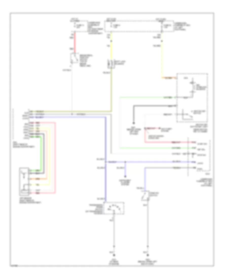
SHIFT INTERLOCK
Shift Interlock Wiring Diagram for Honda Ridgeline RT 2008
List of elements for Shift Interlock Wiring Diagram for Honda Ridgeline RT 2008:
- (2007-08 canada & 2008 usa)
- (at left kick panel)
- (behind upper left end of dash)
- (near ignition key cylinder)
- A12
- A17
- A18
- A24
- A25
- A34
- A35
- Anti-theft system
- App sensor (right rear of engine compartment)
- Aps1
- Aps2
- Atp-p
- Bksw
- Brake pedal position switch (top of brake pedal arm)
- Fuse 13 20a
- Fuse 21 7.5a
- Fuse 32 7.5a
- G101 (at rear of engine)
- G401
- G401 (behind upper left end of dash)
- Hot at all times
- Hot in acc or on
- Hot in on or start
- Ig key sw
- Ignition key switch
- Ignition key switch/key light
- Instrument cluster system
- Key interlock solenoid
- Key sol
- Micu
- N26
- N36
- Nca
- P-pin
- P13
- P15
- P16
- Park pin switch
- Pcm (right rear of engine compartment)
- Red
- Sg3
- Sg4
- Shift lock solenoid
- Sls
- Stop sw
- Transmission range switch (on transmission housing)
- Under-dash fuse/relay box
- Under-dash fuse/relay box (at left kick panel)
- Under-hood fuse/relay box (at right rear of engine compartment)
- Vcc3
- Vcc4
- X34
 English