STARTING/CHARGING
Charging Wiring Diagram for Honda CR-V EX-L 2014

List of elements for Charging Wiring Diagram for Honda CR-V EX-L 2014:
- 12v
- A34
- Alternator
- B16
- B17
- Battery
- Battery sensor
- Brake pedal position switch (top of brake pedal assembly)
- C126
- C133
- C134
- Can-h
- Can-l
- Charging system ind
- Computer data lines system
- D17
- Dc/dv converter
- Driver's junction box 2 (left side of dash)
- Driver's micu
- Eld unit
- Fast controller area network transceiver
- Fuse 1-6 100a
- Fuse 10a
- Fuse 14 10a
- Fuse 2-1 50a
- Fuse 29 10a
- G1 (under battery tray)
- G302 (under left headlight assembly)
- Gauge control module
- Hot in on or start
- Ignition switch
- Indicator drive circuit
- Junction connector c136 (right rear of engine)
- Pcm (left side of engine compt)
- Q16
- Red
- Starting circuit
- T101
- Tan
- Under-dash fuse/relay box (under left end of dash)
- Under-hood fuse/relay box (on left side of engine compt)
- W/o navigation w/ rear entertainment system
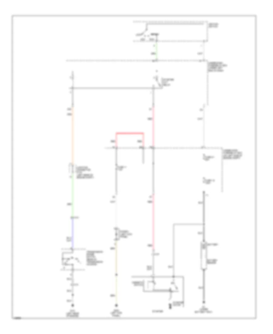
Starting Wiring Diagram for Honda CR-V EX-L 2014
List of elements for Starting Wiring Diagram for Honda CR-V EX-L 2014:
- Acc
- Battery
- Battery sensor
- C131
- C137
- D32
- Diode c (left kick panel)
- Fuse 1-6 100a
- Fuse 11 7.5a
- Fuse 2-1 50a
- G1 (under battery tray)
- G101 (left rear of engine)
- G402 (left kick panel)
- Ignition switch
- Junction connector c134 (left rear of engine compt)
- Lock
- Magnetic switch
- Red
- Run
- Start
- Starter
- Starter cut relay
- Starter motor
- Transmission range switch (rear of transmission housing)
- Under-dash fuse/relay box (under left end of dash)
- Under-hood fuse/relay box (on left side of engine compt)