TRANSMISSION
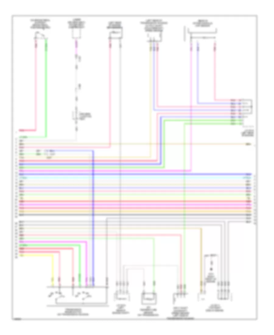
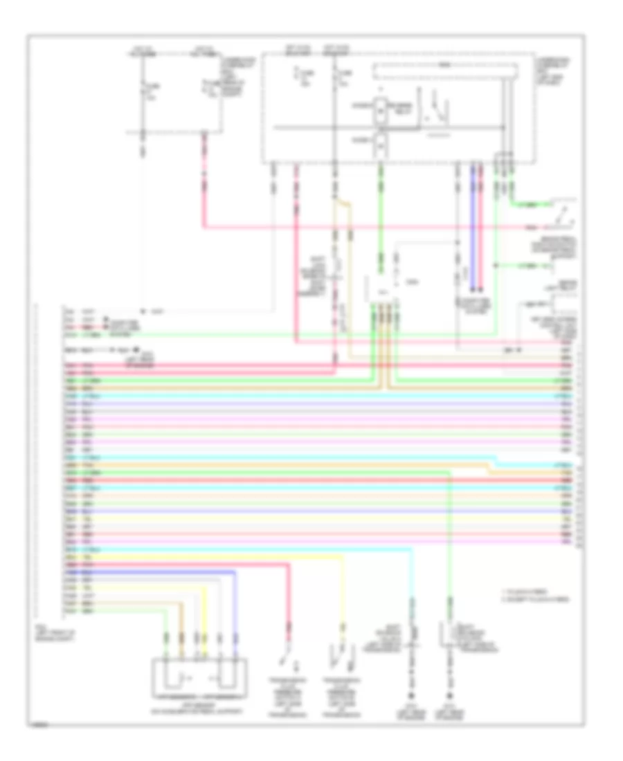
Transmission Wiring Diagram, A/T (1 of 3) for Honda Accord Hybrid Plug-In 2014

List of elements for Transmission Wiring Diagram, A/T (1 of 3) for Honda Accord Hybrid Plug-In 2014:
- (left front of engine compt) brake light relay
- 2nd clutch transmission fluid pressure switch a
- 3rd clutch transmission fluid pressure switch b (left side of transmission)
- A10
- A25
- A27
- A29
- A31
- A42
- A43
- A44
- A45
- A46
- A47
- App sensor (on accelerator pedal support)
- App sensor a
- App sensor b
- B10
- B11
- B20
- B23
- B24
- B25
- B26
- B27
- B28
- B29
- B30
- B34
- B37
- B38
- B39
- B43
- B45
- B48
- C112
- C20
- C207
- C21
- C32
- C33
- C45
- C48
- Ckp sensor (lower left front of engine)
- Computer data lines system
- Diode b
- Diode c
- E10
- E13
- E16
- E17
- Engine controls system
- Fuse 10a
- Fuse 15a
- Fuse 7.5a
- Hot at all times
- Hot in on or start
- J/c c014 (right front of engine)
- Keyless access control unit (left side of dash)
- M11
- Micu
- Pcm (3.5l: right side of engine compt) (2.4l: left side of engine compt)
- Pgm-fi main relay 1
- Pnk
- R10
- Red
- Reverse relay
- Tan
- Under-dash fuse/relay box (left end of dash)
- Under-hood fuse/relay box (left side of engine compt)
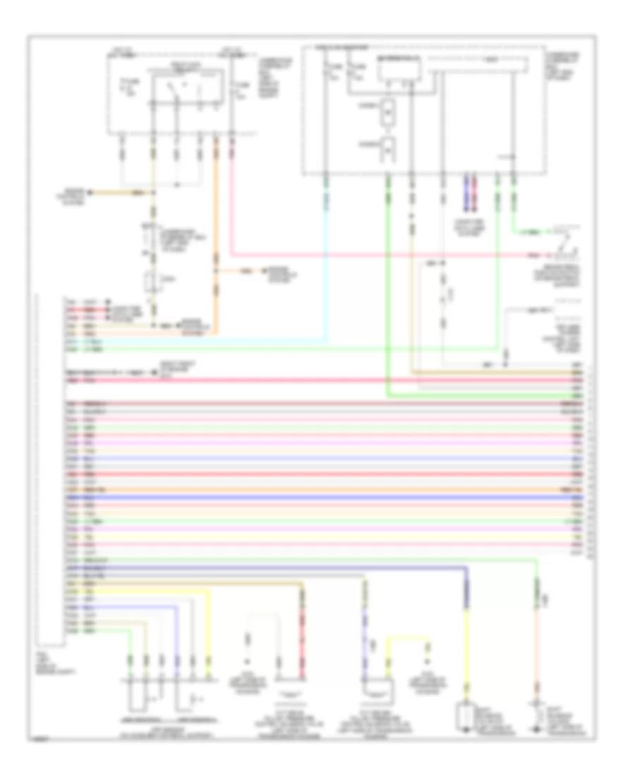
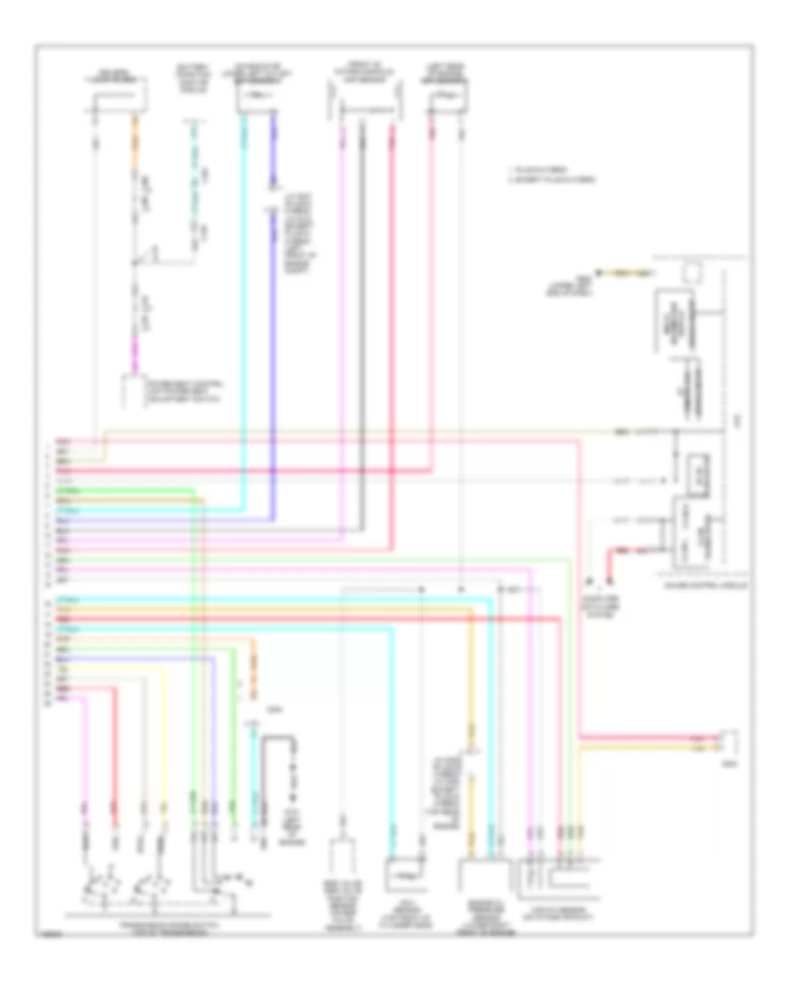
Transmission Wiring Diagram, A/T (2 of 3) for Honda Accord Hybrid Plug-In 2014
List of elements for Transmission Wiring Diagram, A/T (2 of 3) for Honda Accord Hybrid Plug-In 2014:
- (left rear of engine) ect sensor 1
- (left rear of transmission housing) output shaft (countershaft) speed sensor
- (on brake pedal support) brake pedal position switch
- (rear of intake manifold) map sensor
- (under driver's seat) power seat control unit
- Atf temperature sensor (on transmission)
- C109
- C122
- C207
- Driver's junction box
- G101 (right front of engine)
- Input shaft (mainshaft) speed sensor (left side of transmission housing)
- J/c c012 (left rear of engine compt)
- J/c c013 (top right side of engine)
- J/c c015 (left rear of engine)
- Pnk
- Red
- Tan
- Transmission range switch (on transmission housing)
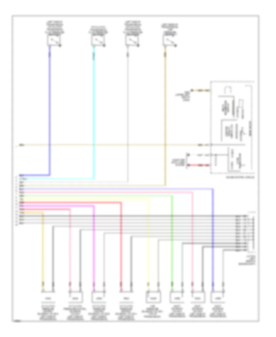
Transmission Wiring Diagram, A/T (3 of 3) for Honda Accord Hybrid Plug-In 2014
List of elements for Transmission Wiring Diagram, A/T (3 of 3) for Honda Accord Hybrid Plug-In 2014:
- (left rear of transmission) line pressure switch
- (left side of transmission) 4th clutch transmission fluid pressure switch c
- (left side of transmission) 6th clutch transmission fluid pressure switch e
- 5th clutch transmission fluid pressure switch d
- A/t clutch pressure control solenoid valve a (left side of transmission)
- A/t clutch pressure control solenoid valve b (left side of transmission)
- A/t clutch pressure control solenoid valve c (left side of transmission)
- A/t clutch pressure control solenoid valve d (left side of transmission)
- A17
- A19
- A20
- A32
- Computer data lines system
- Driver (cog)
- F-can h
- F-can l
- G502 (upper left end of dash)
- Gauge control module
- Information display
- J/c c012 (left rear of engine compt)
- Lcd (dot)
- Lcd (seg)
- Line pressure solenoid valve a (top of transmission)
- Main circuit
- Multi-
- Odo/trip
- Pnk
- Red
- S-matic lcd (seg) at
- Shift solenoid valve a (left side of transmission)
- Shift solenoid valve b (left side of transmission)
- Shift solenoid valve c (left side of transmission)
- Sub pcb
- Tan
- Transceiver f-can
Transmission Wiring Diagram, CVT (1 of 2) for Honda Accord Hybrid Plug-In 2014
List of elements for Transmission Wiring Diagram, CVT (1 of 2) for Honda Accord Hybrid Plug-In 2014:
- (right front of engine) g101
- A11
- A30
- A31
- A37
- A38
- A39
- A40
- A45
- A48
- App sensor (on accelerator pedal support)
- App sensor a
- App sensor b
- B11
- B50
- Brake pedal position switch (on brake pedal support)
- C10
- C112
- C17
- C19
- C204
- C205
- C21
- C23
- C24
- C25
- C26
- C27
- C30
- C302
- C31
- C32
- C33
- C34
- C37
- C41
- C42
- C43
- C44
- C45
- C49
- Computer data lines system
- Cvt drive pulley pressure control solenoid valve (left side of transmission housing)
- Cvt driven pulley pressure control solenoid valve (left side of transmission housing)
- Diode b
- Diode c
- E10
- E13
- E16
- E17
- Engine controls system
- Fuse 10a
- Fuse 15a
- Fuse 7.5a
- G151 (left side of transmission housing)
- Hot at all times
- Hot in on or start
- Keyless access control unit (left side of dash)
- M11
- Micu
- Pcm (left side of engine compt)
- Pgm-fi main relay 1
- Pnk
- R10
- Red
- Reverse relay
- Shift solenoid valve b (left side of transmission)
- Shift solenoid valve o/p (left side of transmission)
- Tan
- Under-dash fuse/relay box (left end of dash)
- Under-hood fuse/relay box (left side of engine compt)
Transmission Wiring Diagram, CVT (2 of 2) for Honda Accord Hybrid Plug-In 2014
List of elements for Transmission Wiring Diagram, CVT (2 of 2) for Honda Accord Hybrid Plug-In 2014:
- (left rear of engine) ect sensor 1
- (left side of transmission housing) cvt clutch pressure control solenoid valve
- (left side of transmission housing) cvt lock-up clutch control solenoid valve
- (on transmission housing) cvt drive pulley pressure sensor
- (right rear of intake manifold) map sensor
- (under driver's seat) power seat control unit
- A17
- A19
- A20
- A32
- C109
- C122
- C204
- C205
- C302
- Computer data lines system
- Cvt driven pulley pressure sensor
- Cvt fluid temperature sensor
- Cvt speed sensor (on transmission housing)
- Driver (cog)
- Driver's junction box
- F-can h
- F-can l
- G101 (right front of engine)
- G152 (left side of transmission housing)
- G502 (upper left end of dash)
- Gauge control module
- Information display
- J/c c011 (lower left front of engine)
- Lcd (dot)
- Lcd (seg)
- Maf/ iat sensor (on intake air duct)
- Main circuit
- Multi-
- Odo/trip
- Pnk
- Red
- S-matic lcd (seg) at
- Sub pcb
- Tan
- Torque converter turbine speed sensor
- Transceiver f-can
- Transmission range switch (top of transmission)
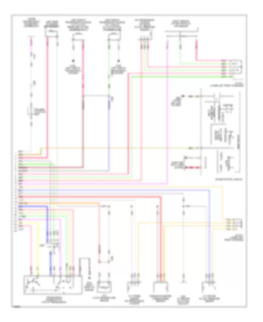
Transmission Wiring Diagram, Hybrid (1 of 2) for Honda Accord Hybrid Plug-In 2014
List of elements for Transmission Wiring Diagram, Hybrid (1 of 2) for Honda Accord Hybrid Plug-In 2014:
- A10
- A13
- A18
- A21
- A28
- A29
- A37
- A38
- A46
- A47
- A48
- App sensor (on accelerator pedal support)
- App sensor a
- App sensor b
- B11
- B15
- B16
- B18
- B21
- B22
- B23
- B24
- B26
- B27
- B29
- B30
- B34
- B41
- B46
- B47
- B48
- B49
- B50
- B51
- Brake light relay
- Brake pedal position switch (on brake pedal support)
- C112
- C113
- C203
- C21
- C40
- C41
- C50
- Computer data lines system
- Diode a
- Diode b
- E16
- E17
- E23
- Except plug-in hybrid
- F11
- Fuse 10a
- Fuse 15a
- G101 (left rear of engine)
- Hot at all times
- Hot in on or start
- Keyless access control unit (left side of dash)
- M11
- M12
- Micu
- Pcm (left front of engine compt)
- Plug-in hybrid
- Pnk
- R10
- Red
- Reverse relay
- Shift lock solenoid (base of shift lever assembly)
- Shift solenoid valve a (left side of transmission)
- Shift solenoid valve b (left side of transmission)
- Tan
- Transmission fluid pressure switch a (left side of transmission)
- Transmission fluid pressure switch b (left side of transmission)
- Under-dash fuse/relay box (left end of dash)
- Under-hood fuse/relay box (left rear of engine compt)
Transmission Wiring Diagram, Hybrid (2 of 2) for Honda Accord Hybrid Plug-In 2014
List of elements for Transmission Wiring Diagram, Hybrid (2 of 2) for Honda Accord Hybrid Plug-In 2014:
- (front of intake manifold) map sensor
- (left rear of engine) ect sensor 1
- (on radiator lower left outlet) ect sensor 2
- A17
- A19
- A20
- A32
- Battery condition monitor module
- C108
- C109
- C125
- C126
- C132
- C203
- C21
- C401
- Computer data lines
- Converter dc-dc
- Cpu
- Drive circuit
- Driver's junction box
- Egr valve/ egr valve position sensor (on egr valve assembly)
- Engine oil pressure sensor (lower right front of engine)
- Except plug-in hybrid
- F-can h
- F-can l
- Fwd
- Fwd2
- G101 (left rear of engine)
- G502 (upper left end of dash)
- Gauge control module
- Gnd
- Information display
- Inta sensor (top front of cylinder head)
- J/c c006 (plug-in hybrid) j/c c005 (except plug-in hybrid) (top rear of engine)
- J/c c007 (plug-in hybrid) j/c c012 (except plug-in hybrid) (left front of engine compt)
- Maf/iat sensor (on intake air duct)
- Multi-
- Plug-in hybrid
- Pnk
- Power seat control unit/power seat adjustment switch
- Red
- Rvs
- Rvs2
- S-matic lcd at
- System
- Tan
- Transceiver f-can
- Transmission range switch (top of transmission)