TRANSMISSION
4WD Wiring Diagram for Honda Pilot EX 2005

List of elements for 4WD Wiring Diagram for Honda Pilot EX 2005:
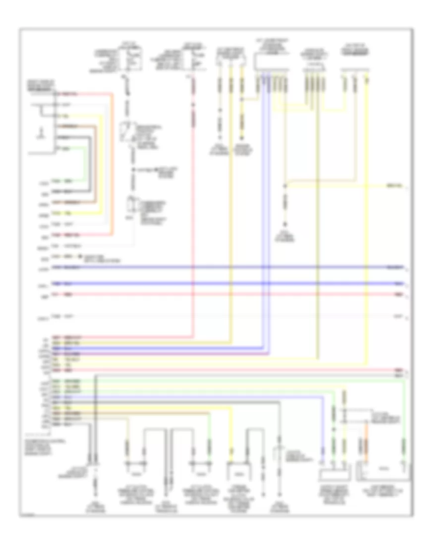
A/T Wiring Diagram (1 of 3) for Honda Pilot EX 2005
List of elements for A/T Wiring Diagram (1 of 3) for Honda Pilot EX 2005:
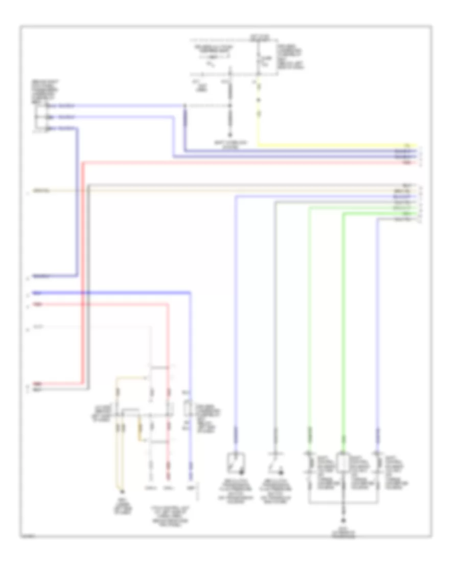
A/T Wiring Diagram (2 of 3) for Honda Pilot EX 2005
List of elements for A/T Wiring Diagram (2 of 3) for Honda Pilot EX 2005:
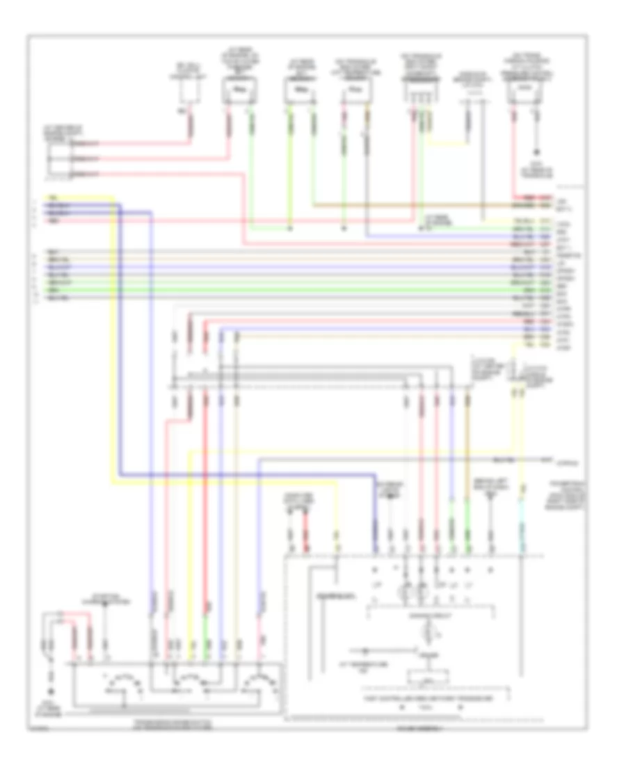
A/T Wiring Diagram (3 of 3) for Honda Pilot EX 2005
List of elements for A/T Wiring Diagram (3 of 3) for Honda Pilot EX 2005: