ANTI-LOCK BRAKES
Anti-lock Brake Wiring Diagrams for Lincoln Blackwood 2002
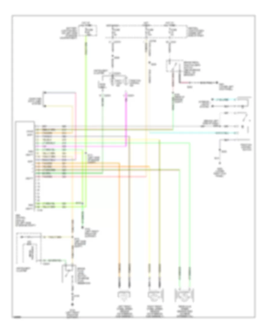
List of elements for Anti-lock Brake Wiring Diagrams for Lincoln Blackwood 2002:
- (behind left side of dash) s250
- Abs control module (on left side of engine compt)
- Anti- lock ind
- Battery junction box (on left side of engine compartment)
- Bias ckt
- Brake fluid level switch (on brake fluid reservoir)
- Brake pedal position (bpp) switch (above brake pedal, on bracket)
- C146
- C220a
- C243
- C270a
- C270b
- Central junction box (under left side of dash)
- Computer data lines system
- Fuse 10a
- Fuse 50a
- Fuse 5a
- G104 (left front radiator support)
- G200 (lower right kick panel)
- G201 (lower left kick panel)
- Gnd
- Hot at all times
- Hot in run
- Instrument cluster
- Interior lights system
- Left front wheel speed sensor (on steering hub assembly)
- Nca
- Ohm
- Processor micro-
- Rear axle speed sensor (dss) (on rear differential)
- Right front wheel speed sensor (on steering hub assembly)
- S106
- S160 (rear of engine compt)
- S170 (left side of engine compt)
- S171 (left side of engine compt)
- S172
- S202
- S208
- S228
- S265
- Scp+
- Scp-
- Tan/red
- Traction control ind
- Traction control switch
- Vbatt
- Vpwr
 English