ENGINE PERFORMANCE
4.6L
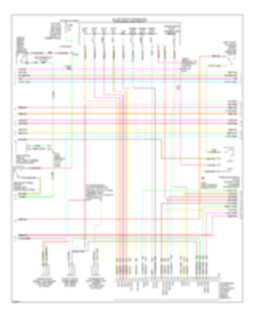
4.6L, Engine Performance Wiring Diagram (1 of 4) for Lincoln Aviator 2005

List of elements for 4.6L, Engine Performance Wiring Diagram (1 of 4) for Lincoln Aviator 2005:
- (cdx6)
- (dm100)
- (in dash panel to engine wiring harn, near breakout to powertrain control module) s135
- (near breakout
- (near breakout to c133)
- (near breakout to c238)
- (near breakout to low pitch horn)
- (near breakout to variable assist power steering module)
- A/c sw
- Acp sw in
- Air conditioning system
- Audio unit
- Battery
- Battery junction box (bjb) (left side of engine compartment, at fender apron)
- Boo sw
- C175b
- C2231a
- C2253c
- C240b
- C290a
- Can vent
- Cool fan
- Cooling fans system
- Cruise control system
- Data link connector, obd ii (behind left side of dash)
- Evap pu
- Evaporative emission (evap) canister vent valve (left rear of vehicle)
- F pmp mtr
- Feps in
- Fuse 10a
- Fuse 15a
- Fuse 25a
- Fuse 40a
- G107 (left side of engine compt)
- G108 (right rear of engine compt)
- Ground
- Hot at all times
- Hot in run or start
- Iat in
- Ign
- Ind ctrl
- Ind input
- Maf out
- Mass airflow (maf) sensor (right front of engine compartment on fender)
- Navigation
- Navigation electronic control unit module (bottom of rear cargo area)
- Passive anti-theft transceiver
- Pcm diode
- Pcm power relay
- Power steering pressure switch (in front of engine compt)
- Powertrain control module (pcm) (at right side of engine firewall)
- Pres sw
- Psps vref
- Red
- Red/pnk
- Return
- Rly ctrl
- Rx sig
- S106 (near breakout to c210)
- S110
- S117
- S118 (in dash panel to engine wiring harness, near breakout to engine cooling fan motor)
- S124
- S128
- S147
- S149
- S155
- S225
- S230
- Scc
- Scm a
- Scm b
- Scm c
- Scp bus +
- Scp bus -
- Sens rtn
- Shift interlock system
- Spd sw
- St mtr
- Starting/charging system
- Tank press
- Tcs ocs
- To speed control actuator)
- Tps out
- Transmissions system
- Tx sig
- V ref
- Vapor management valve (left side of engine compt)
- Variable assist power steering module (behind right side of dash)
- Vss
- Windshield wiper motor (on left side of engine compt firewall)
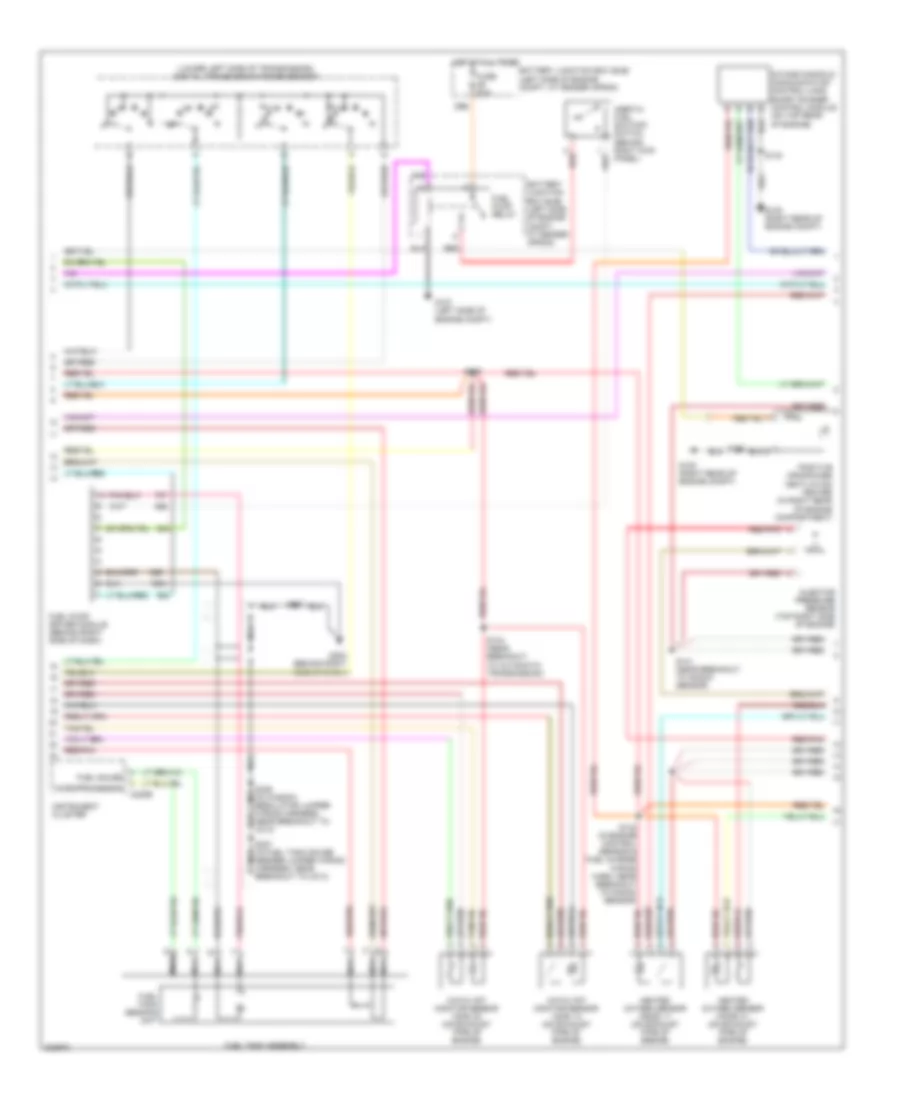
4.6L, Engine Performance Wiring Diagram (2 of 4) for Lincoln Aviator 2005
List of elements for 4.6L, Engine Performance Wiring Diagram (2 of 4) for Lincoln Aviator 2005:
- (above brake pedal) brake pedal position switch
- (in transmission control selector neutral switch wiring harness, near breakout to automatic transmission) s105
- (left front of engine compt) a/c high pressure switch
- (near breakout to c133) s112
- (near breakout to powertrain control module) s127
- (on left side of transmission) transmission hardware unit
- Abs control module (left front corner of engine compt)
- Battery junction box (bjb) (left side of engine compt, at fender apron)
- C175t
- Epc sol
- Fuse 15a
- G108 (right rear of engine compt)
- H2os 12 htr
- H2os 12 in
- H2os 22 htr
- H2os 22 in
- Hot at all times
- Intermediate shaft speed (iss) sensor (top left side of trans)
- Iss
- Oss
- Output shaft speed sensor (left rear of trans)
- Pcs b
- Pcs c
- Powertrain control module (pcm) (at right side of engine firewall)
- Press ctrl sol a
- Press ctrl sol b
- Press ctrl sol c
- Red/pnk
- Redundant pedal switch (under left side of dash panel)
- S109
- S116 (near breakout to low pitch horn)
- S235
- Shift sol a
- Shift sol b
- Shift sol c
- Shift sol d
- Sig rtn
- Ss a
- Ss b
- Ss c
- Ss d
- Tcc sol
- Tft
- Thermo expansion valve (on right side of engine compartment)
- Tr1
- Tr2
- Tr3a
- Tr4
- Transmission fluid temperature sensor
- Tss
- Turbine shaft speed (tss) sensor (top left side of trans)
4.6L, Engine Performance Wiring Diagram (3 of 4) for Lincoln Aviator 2005
List of elements for 4.6L, Engine Performance Wiring Diagram (3 of 4) for Lincoln Aviator 2005:
- (lower left side of transmission) digital transmission range sensor
- Battery junction box (bjb) (left side of engine compt, at fender apron)
- C220b
- Catalyst monitor sensor (cms) 12 (on exhaust pipe of engine)
- Catalyst monitor sensor (cms) 22 (on exhaust pipe of engine)
- Fuel gauge
- Fuel pump driver module (behind right side of dash)
- Fuel pump relay
- Fuel tank assembly
- Fuel tank sending unit
- Fuse 20a
- G107 (left side of engine compt)
- G108 (right rear of engine compt)
- G202 (behind right side of dash)
- Heated oxygen sensor (ho2s) 11 (on exhaust pipe of engine)
- Heated oxygen sensor (ho2s) 21 (on exhaust pipe of engine)
- Hot at all times
- Inertia fuel shutoff switch (behind right kick panel)
- Injector pressure sensor (top right side of engine)
- Instrument cluster
- Intake manifold communication control-long short runner control module (on top rear of engine)
- Microprocessor
- N r
- Nca
- Positive crankcase ventilation heater (in right rear of engine compartment)
- Red
- Red/pnk
- S104 (near breakout to automatic transmission)
- S125
- S140
- S141 (near breakout to knock sensor)
- S142 (in engine control sensor & fuel charge wiring harn, near breakout to knock sensor)
- S227
- S307 (in fuel tank gauge sender jumper wiring nca harness, near breakout to c313)
- S336 (in window regulator jumper nca
- Wiring harness, near breakout to c313)
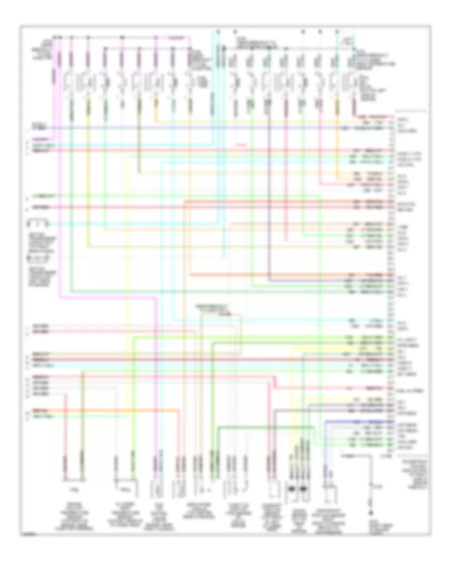
4.6L, Engine Performance Wiring Diagram (4 of 4) for Lincoln Aviator 2005
List of elements for 4.6L, Engine Performance Wiring Diagram (4 of 4) for Lincoln Aviator 2005:
- (near breakout to injector 4) s144
- C175e
- Camshaft position sensor (top front of left cylinder head)
- Ckp sens +
- Ckp sens -
- Cmp sens
- Coil on plug (on top left side of engine)
- Cop 1
- Cop 2
- Cop 3
- Cop 4
- Cop 5
- Cop 6
- Cop 7
- Cop 8
- Crankshaft position sensor (right front of engine behind a/c compressor)
- Cyl input
- Cylinder head temperature sensor (on right rear of cylinder head)
- Dfpe sens
- Ect sens
- Egr system module (top center rear of engine)
- Engine coolant temperature sensor (top right of engine, near injector harness)
- Evr ctrl
- Fuel inj pres
- Fuel injec- tors
- G108 (right rear of engine compt)
- Ho2s 11
- Ho2s 11 htr
- Ho2s 21
- Ho2s 21 htr
- Iac ctrl
- Idle air control valve (top of engine, near throttle body)
- Ignition transformer capacitor 1 (left rear of engine)
- Ignition transformer capacitor 2 (top right rear of eng)
- Imcc-lsrc
- Inj 1
- Inj 2
- Inj 3
- Inj 4
- Inj 5
- Inj 6
- Inj 7
- Inj 8
- Knock sensor (on top rear of engine)
- Ks 1
- Ks 2
- Map sig
- Nca
- Pnk/
- Powertrain control module (pcm) (at right side of engine firewall)
- Red/pnk
- Return
- S138 (near breakout to egr system module)
- S139
- S143 (near breakout to cylinder head temperature sensor)
- S145 (near breakout to fuel injector)
- S146 (near breakout to fuel injector)
- Tan
- Tan/red
- Throttle position (tps) sensor (on top of engine)
- Tps
- V ref