TRANSMISSION
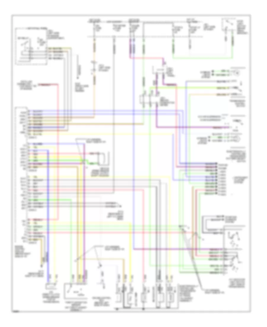
Transmission Wiring Diagram for Lexus LS 400 1995
List of elements for Transmission Wiring Diagram for Lexus LS 400 1995:
- (i/p harness, right side of i/p)
- 2 indic
- 3 indic
- A/t indicator light switch (left side of transmission)
- A/t oil temp
- A10
- B14
- B17
- Batt
- Conn a
- Conn b
- Conn c
- Conn d
- Cruise control ecu (behind left side of dash)
- D indic
- Data link connector 1 (top front of engine)
- E18
- Ect
- Efi fuse 20a
- Efi relay
- Electronically controlled transmission pattern select switch
- Electronically controlled transmission solenoid (in trans. valve body assembly)
- Engine control module (behind right side of i/p)
- Eo1
- Eo2
- Eo3
- G100 (front side of left fender)
- G114 (rear side of left cylinder head)
- G117 (rear side of right cyl head)
- Gauge fuse 10a
- Hot at all times
- Hot in on or start
- Hot in start
- Idl1
- Ign fuse 10a
- Igsw
- Instrument cluster system
- Interior lights system
- J/b 1 (left side of dash)
- J/b 2 (left side of engine compartment)
- J/b 3 (behind combination meter)
- J/b 4 (left kick panel)
- J/c 4 (left side of dash)
- K11
- L indic
- L11
- Mrel
- Mt3
- Mtd
- N indic
- N0.3 (lock-up)
- Nco+
- Nco-
- No. 1
- No. 2
- No. 4
- Normal
- Nssd
- Nsw
- O/d direct clutch speed sensor (top of transmission)
- Oil
- P indic
- Power
- Pwr
- Pwr ind
- Pwrl
- R indic
- Red
- Sln+
- Sln-
- Slu+
- Slu-
- Sp2+
- Sp2-
- Starter fuse 7.5a
- Starting/ charging system
- Stop light switch (brake pedal bracket)
- Stop lp fuse 25a
- Stop s fuse 5a
- Te1
- Throttle position sensor (on throttle body assembly)
- Transmission control switch
- Vehicle speed sensor (trans. output shaft housing)
- Vta1
- Vta2
- W/air suspension
- W/o air suspension
 English