AIR CONDITIONING
A/C Wiring Diagram for Ford Contour SE 1997

List of elements for A/C Wiring Diagram for Ford Contour SE 1997:
- (behind bottom of right kick panel)
- (engine cooling fan harness, near electric cooling fan motor breakout)
- (fuse box harn, behind left side of i/p)
- (i/p harn, behind right center of i/p)
- (left front of engine compartment, behind headlamp)
- (right front of engine compartment, near headlamps)
- (right front of engine compt, near headlamps)
- 14s
- 2.0l
- 2.5l
- 91s
- A/c clutch cycling pressure switch (left front of engine compartment)
- A/c clutch diode
- A/c clutch relay (in engine compartment fuse box)
- A/c clutch solenoid
- A/c high pressure cutout/fan switch (right front corner of engine compartment)
- A/c wide open throttle relay (in engine compartment fuse box)
- Air temperature actuator (under right center of i/p, left of glove box)
- Air temperature control
- Backup lamps fuse 23 15a
- Blower motor
- Blower motor fuse 37 30a
- Blower motor relay
- Blower motor resistor (under right center of i/p)
- Blower switch
- C281
- Clutch switch
- Cool
- Cooling fan resistor (lower left corner of cooling fan shroud)
- Def
- Electric cooling fan motor
- Electric cooling fan motor #1
- Electric cooling fan motor #2
- Engine compartment fuse box
- Engine compt)
- Engine cooling fan fuse 2 60a
- Fan switch
- Flr
- Flr/def
- G100
- G100 (left front of engine compartment, behind headlamp)
- G101
- G101 (right front of engine compart- ment, near headlamps)
- G203
- G203 (behind bottom of right kick panel)
- Gearshift lever unit
- Heater/ a/c mode switch
- High speed cooling fan relay (in engine compartment fuse box)
- Hot at all times
- Hot in run or start
- Interior fuse panel
- Low speed cooling fan relay (in engine compartment fuse box)
- Max a/c
- Nca
- Norm a/c
- Off
- Pan/flr
- Pan/vnt
- Pcm power relay
- Powertrain control module (right rear corner of engine compartment)
- Red
- S107 (fuse box harn, left side of engine compt)
- S124
- S124 (engine cooling fan harness, near electric cooling fan motor breakout)
- S125 (engine cooling fan harn, right front side of engine compt)
- S126 (engine cooling fan harn, near a/c clutch solenoid)
- S167 (engine control harn, near pcm breakout)
- S171 (fuse box harn, front center of engine compt)
- S216 (i/p harn, near i/p cluster breakout)
- S218
- S223 (i/p harn, near main light sw breakout)
- S242
- S243 (fuse box harn, behind left side of i/p)
- S245 (i/p harn, near top of glove box)
- S247 (i/p harn, near top of glove box)
- Shorting bar connector #1 (behind left side of i/p)
- Shorting bar connector #3 (behind right side of i/p)
- Warm
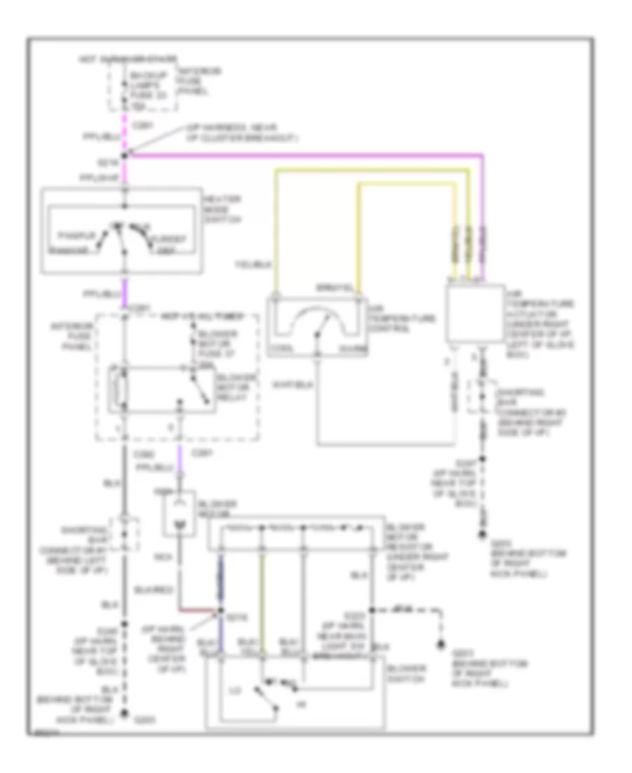
Heater Wiring Diagram for Ford Contour SE 1997
List of elements for Heater Wiring Diagram for Ford Contour SE 1997:
- (behind bottom
- (i/p harn, behind right center of i/p)
- (i/p harness, near i/p cluster breakout)
- Air temperature actuator (under right center of i/p, left of glove box)
- Air temperature control
- Backup lamps fuse 23 15a
- Blower motor
- Blower motor fuse 37 30a
- Blower motor relay
- Blower motor resistor (under right center of i/p)
- Blower switch
- C281
- C282
- Cool
- Def
- Flr
- Flr/def
- Fuse
- G203
- G203 (behind bottom of right kick panel)
- Heater mode switch
- Hot at all times
- Hot in run or start
- Interior
- Interior fuse panel
- Kick panel)
- Nca
- Of right
- Off
- Pan/flr
- Pan/vnt
- Panel
- S216
- S218
- S223 (i/p harn, near main light sw breakout)
- S245 (i/p harn, near top of glove box)
- Shorting bar connector #1 (behind left side of i/p)
- Shorting bar connector #3 (behind right side of i/p)
- Warm
 English