AIR CONDITIONING
A/C Wiring Diagram, Auto A/C for Ford Crown Victoria 1997

List of elements for A/C Wiring Diagram, Auto A/C for Ford Crown Victoria 1997:
- (engine harn, left rear of eng compt) s110
- (engine harn, near right front fender)
- (i/p harn, behind center of i/p)
- (i/p harn, behind right side of i/p) s200
- (i/p harn, behind top left side of i/p)
- (i/p harn, near data link conn (dlc) breakout)
- (i/p harn, near glove box lamp breakout)
- (not used)
- (top of engine, near fuel injector 1)
- A/c compressor clutch
- A/c clutch cycling pressure switch (right rear of engine compartment)
- A/c clutch diode
- A/c clutch out
- A/c cutout relay (in relay center)
- A/c high pressure cut out switch (right side of engine compartment)
- A/c plenum)
- Ambient temp input
- Ambient temperature sensor (center front of vehicle, on upper radiator support)
- Battery
- Blend door act
- Blend door actuator (behind right side of i/p, top of
- Blend door pot
- Blend door ref
- Blower motor
- Blower motor speed
- Blower motor speed controller (top right center of safety wall)
- Blower spped fback
- C227
- C228
- Cooling fan
- Cooling fan fuse 50a
- Cooling fan relay (engine compartment fuse box)
- Data link (+)
- Data link (-)
- Data link connector (dlc) (behind left side of i/p)
- Electronic automatic temperature control (eatc) module (center of i/p)
- Eng/met conv
- Engine compartment fuse box
- Fuse 15a
- Fuse 30a
- G101 (front of right front fender apron)
- G134
- Ground
- Hot at all times
- Hot in run
- I/p fuse panel
- Ignition
- Illumination
- In car temp sens
- In-car temperature sensor (behind top center of i/p)
- Instrument cluster (digital)
- Interior lights system
- Pcm power relay
- Powertrain control module (pcm) (behind left side of i/p)
- Red
- Relay signal
- S113
- S117
- S118
- S206
- S226
- S227 (i/p harness, behind left side of i/p)
- S251
- Sensor ground
- Sun load sensor (top right side of i/p, above glove box)
- Sunload sens input
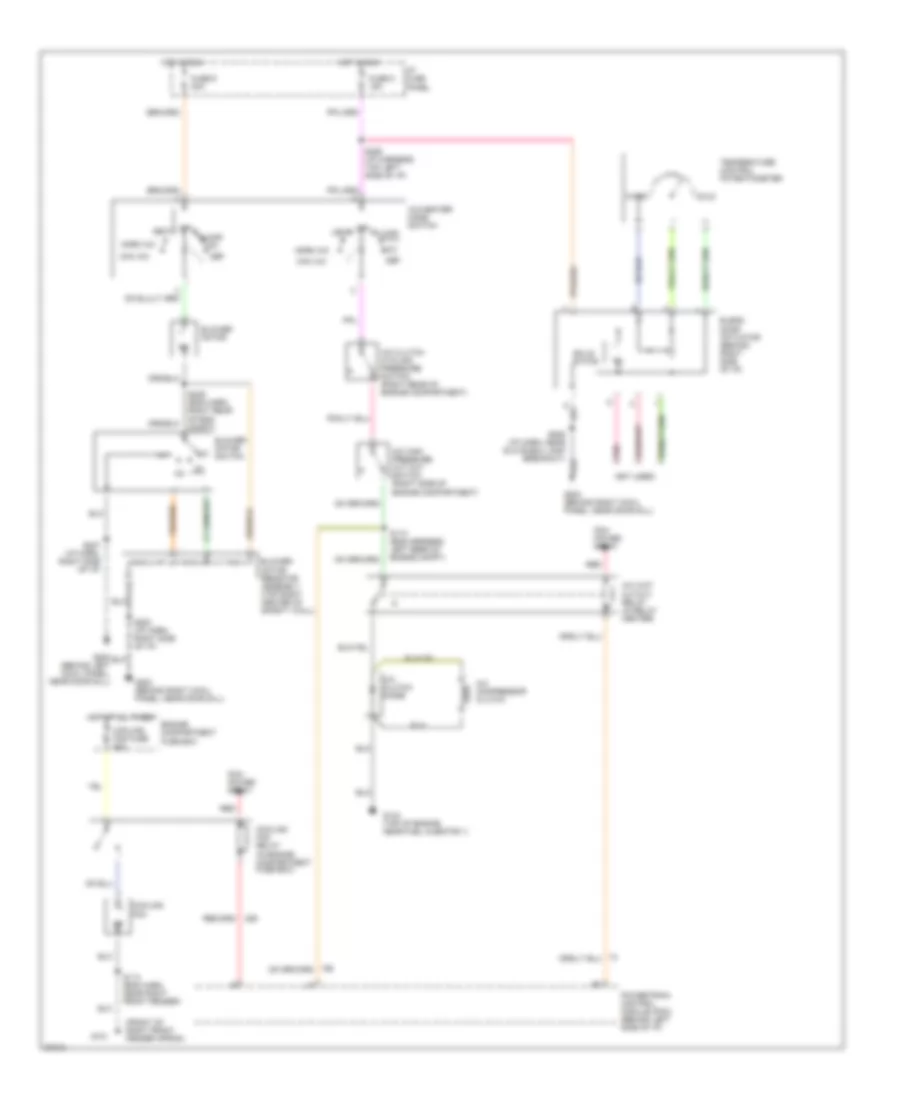
A/C Wiring Diagram, Manual A/C for Ford Crown Victoria 1997
List of elements for A/C Wiring Diagram, Manual A/C for Ford Crown Victoria 1997:
- (front of right front fender apron)
- (not used)
- A/c clutch cycling pressure switch (right rear of engine compartment)
- A/c clutch diode
- A/c compressor clutch
- A/c high pressure cut out switch (right side of engine compartment)
- A/c wot cutout relay (in relay center)
- A/c-heater mode switch
- Blend door actuator (behind right side of i/p)
- Blower motor
- Blower motor resistor assembly (top right center of safety wall)
- Blower motor switch
- Cold
- Cooling fan
- Cooling fan fuse 50a
- Cooling fan relay (in engine compartment fuse box)
- Def
- Engine compartment fuse box
- Floor
- Fuse 5 15a
- Fuse 9 30a
- G101
- G134 (top of engine near fuel injector 1)
- G200 (behind left cowl panel, near door sill)
- G203 (behind right cowl panel, near door sill)
- Hot at all times
- Hot in run
- I/p fuse panel
- Max a/c
- Mix
- Norm a/c
- Off
- Pcm power relay
- Pnk
- Powertrain control module (pcm) (behind left side of i/p)
- Red
- S110 (eng harness, left rear of engine compt)
- S113 (eng harn, near right front fender)
- S200 (i/p harn, right side of i/p)
- S206 (i/p harn, near glove box lamp breakout)
- S207 (i/p harn, right side of i/p)
- S226 (i/p harness, top left side of i/p)
- S239 (eng harn, right rear of eng compt)
- Solid state
- Temperature control potentiometer
- Vent
- Warm