AIR CONDITIONING
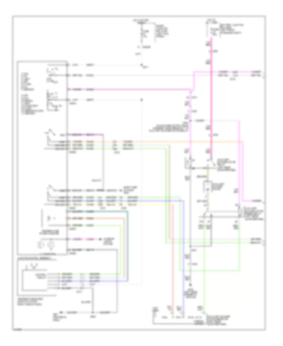
Manual A/C Wiring Diagram, with Stripped Chassis for Ford Cutaway E250 2011

List of elements for Manual A/C Wiring Diagram, with Stripped Chassis for Ford Cutaway E250 2011:
- (4.6l: engine control sensor wiring harness & fuel charge, near breakout to evap canister purge valve) (6.8l: engine control sensor wiring harness & fuel charge, in breakout to powertrain control module (pcm)) s172
- (not used)
- 4.6l & 5.4l
- 6.8l
- A/c clutch relay
- A/c compressor clutch field coil (lower right front of engine)
- Accr
- Accs
- Battery junction box (bjb) (left front of engine compt)
- Blower motor relay
- C134
- C1551b
- C1551e
- C175b
- C175e
- C2095
- C2280b
- C237
- C291
- Ce302
- Ch302
- Ch421
- Cht
- Customer access
- Cylinder head temperature sensor (front of left cylinder head)
- Engine controls system
- Except 5.4l
- Fuse 10a
- Fuse 40a
- Fuse 50a
- G100 (right side of engine compt)
- G101 (left front corner of engine compt)
- Hot at all times
- Hot in start or run
- Pcm power relay
- Pcmrc
- Powertrain control module (pcm) (center rear of engine compt)
- Re405
- S108
- S116
- S123
- S124
- S129
- Sigrtn
- Smart junction box (sjb) (left side of dash)
- Ve712
Manual A/C Wiring Diagram, without Stripped Chassis (1 of 2) for Ford Cutaway E250 2011
List of elements for Manual A/C Wiring Diagram, without Stripped Chassis (1 of 2) for Ford Cutaway E250 2011:
- (center of dash)
- (not used)
- (right side of dash) g200
- 0) off 5) max 6) normal 7) vent 8) floor/vent 9) floor 10) defrost/floor 11) defrost
- 1) max 2) a/c 3) vent 4) off 5) floor 6) mix 7) defrost
- 87a
- Auxiliary blower motor
- Auxiliary blower motor relay (left rear quarterpanel)
- Auxiliary blower motor resistor (left rear quarterpanel)
- Auxiliary blower motor speed relay (left rear quarterpanel)
- Battery junction box (bjb) (left front of engine compt)
- C210
- C214
- C219
- C2280b
- C264
- C294a
- C294b
- C294c
- C294d
- C294e
- C405
- Cbp37
- Ch202
- Ch203
- Ch204
- Ch428
- Ch429
- Ch430
- Ch434
- Ch435
- Cha06
- Cha07
- Cha08
- Circuit
- Climate control assembly
- Control
- Fuse 10a
- Fuse 50a
- G201
- G403 (left rear corner of vehicle)
- Gd115
- Gd116
- Gnd
- High
- Hot at all times
- Hot in start or run
- Illumination
- Interior lights system
- Mid high
- Mid low
- S217
- S264
- S265
- S400 (a/c blower motor wiring harness, near breakout to auxiliary blower motor relay)
- S401
- Smart junction box (sjb) (left kick panel)
- Temperature blend door actuator (right side of dash)
- Temperature potentiometer
- Thermal limiter
- Vlno4
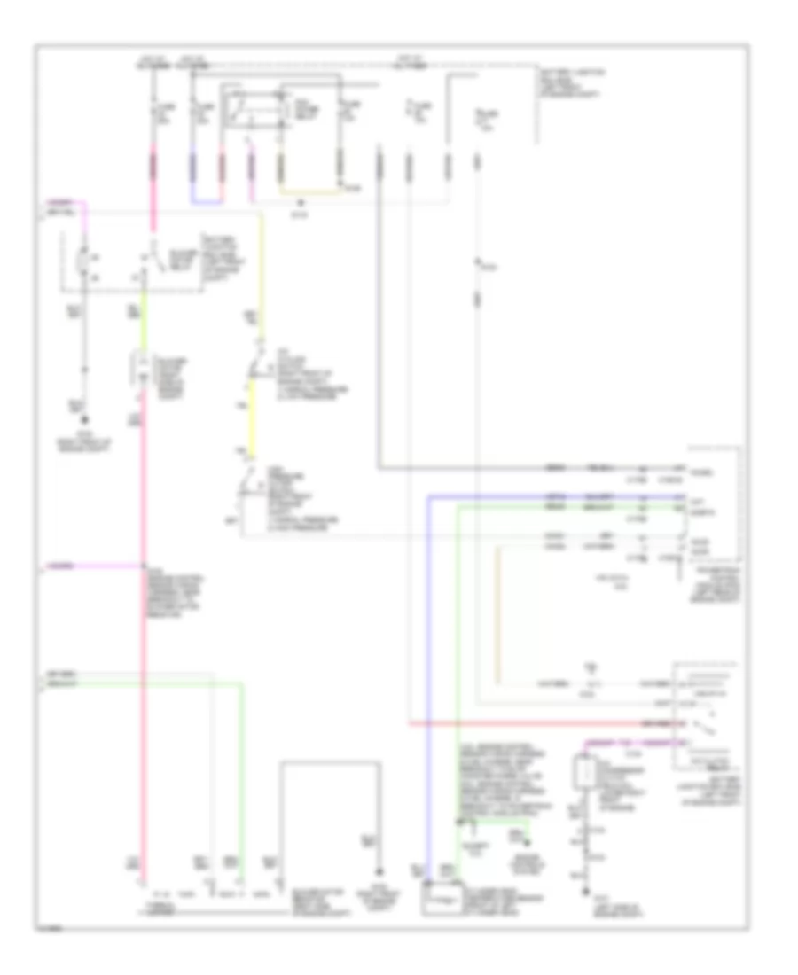
Manual A/C Wiring Diagram, without Stripped Chassis (2 of 2) for Ford Cutaway E250 2011
List of elements for Manual A/C Wiring Diagram, without Stripped Chassis (2 of 2) for Ford Cutaway E250 2011:
- (4.6l: engine control sensor wiring harness & fuel charge, near breakout to evap canister purge valve) (6.8l: engine control sensor wiring harness & fuel charge, in breakout to powertrain control module (pcm)) s172
- (left side of engine compt)
- (right front of engine compt)
- 1) normal pressure 2) high pressure
- 1) normal pressure 2) low pressure
- 4.6l & 5.4l
- 6.8l
- A/c clutch relay
- A/c compressor clutch field coil (lower right front of engine)
- A/c cycling switch
- Accr
- Accs
- Battery junction box (bjb) (left front
- Battery junction box (bjb) (left front of engine compt)
- Blower motor (right side of engine compt)
- Blower motor relay
- Blower motor resistor (right side of engine compt)
- C134
- C1551b
- C1551e
- C175b
- C175e
- Ce302
- Ch302
- Ch421
- Cht
- Compt)
- Cylinder head temperature sensor (front of left cylinder head)
- Engine controls system
- Except 5.4l
- Fuse 10a
- Fuse 40a
- Fuse 50a
- G100 (right front of engine compt)
- G101
- High pressure cutoff
- Hot at all times
- Of engine
- Of engine compt)
- Pcm power relay
- Pcmrc
- Powertrain control module (pcm) (left rear of engine compt)
- Re405
- S105 (engine control sensor wiring harness, near breakout to blower motor resistor)
- S116
- S123
- S124
- S129
- Sigrtn
- Switch (right front of engine compt)
- Thermal limiter
- Ve712