AIR CONDITIONING
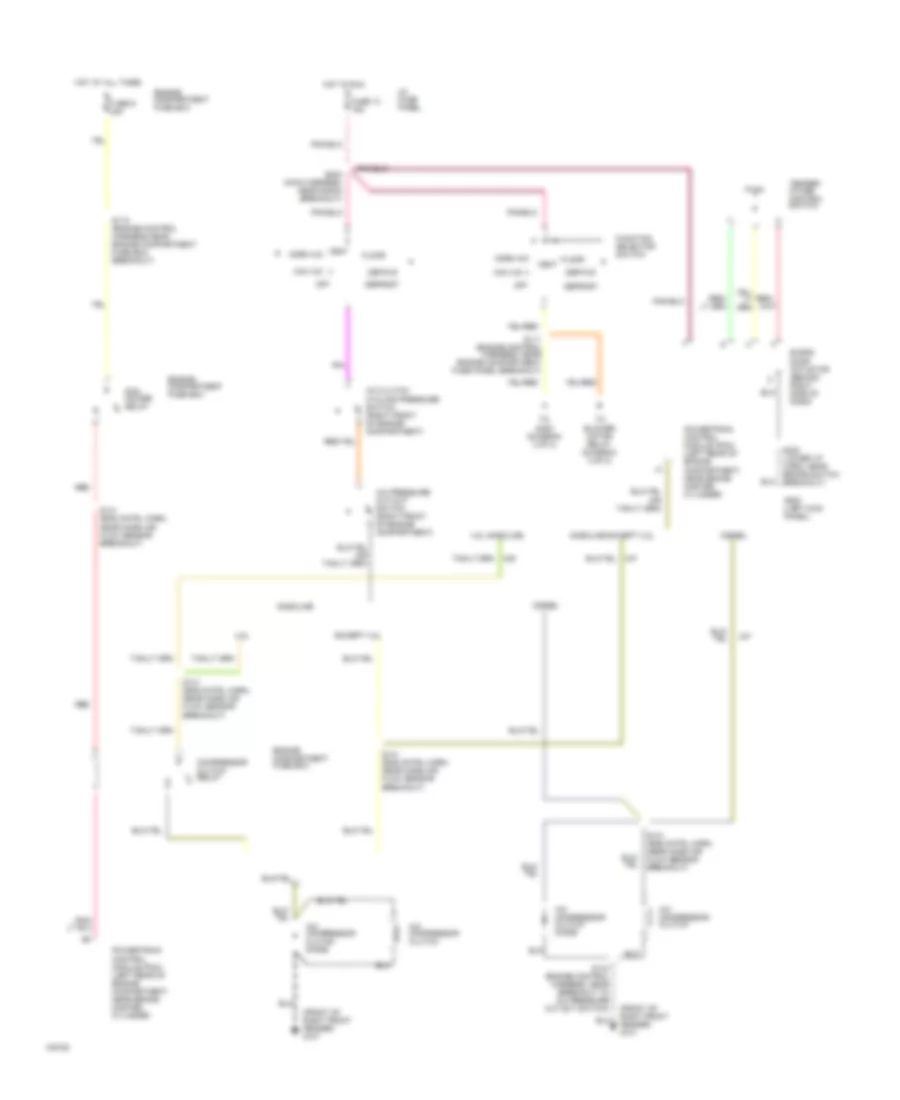
Heater Wiring Diagram for Ford Econoline E150 1999

List of elements for Heater Wiring Diagram for Ford Econoline E150 1999:
- (not used)
- (rear harness, near breakout along left "b" pillar, near roof)
- Auxi- liary high blower motor relay (left rear corner of vehicle, above wheelwell)
- Auxiliary blower motor
- Auxiliary blower motor relay (left rear corner of vehicle, above wheelwell)
- Auxiliary blower resistor (left rear corner of vehicle, above wheelwell)
- Auxiliary heater blower switch
- Blend door actuator (behind center of dash, on a/c heater plenum)
- Blower motor
- Blower motor relay
- Blower motor resistor (right rear of engine compartment, near blower motor)
- Cutaways
- Def
- Def/flr
- Engine compartment fuse box
- Floor
- Front blower switch
- Function selector switch
- Fuse 13 15a
- Fuse 13 50a
- Fuse 16 50a
- G100 (front of left front fender)
- G101 (front of right front fender)
- G203 (behind upper left side of dash, near kick panel)
- G204 (left kick panel)
- G400 (left rear corner of vehicle, near left rear door)
- Hot at all times
- Hot in run
- I/p fuse panel
- Off
- Rear auxiliary blower switch
- S111 (engine control harness, near engine compt. fuse panel breakout)
- S122 (engine control harness, left rear of engine compartment on kick panel)
- S143 (engine control harness, near breakout to a/c pressure cut-out switch)
- S144 (engine control harn, right front corner of engine compartment)
- S202 (main harn, near radio breakout)
- S202 (main harness, near radio breakout)
- S203 (main harness, near radio breakout)
- S223 (lower dash harn, near brake switch breakout)
- S257 (lower dash harness, behind left "b" pillar, near floor)
- S303
- S304
- S305
- S400 (window regulator relay switch harness, near breakout behind left "b" pillar)
- S401 (auxiliary blower motor harness, near auxiliary blower motor breakout)
- Temper- ature control switch
- Vans & wagons
- Vent
- W/ rear control
- W/o rear con- trol
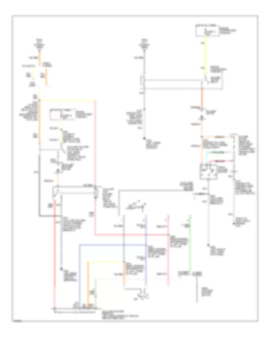
Manual A/C Wiring Diagram (1 of 2) for Ford Econoline E150 1999
List of elements for Manual A/C Wiring Diagram (1 of 2) for Ford Econoline E150 1999:
- (front of right front fender) g101
- 4.2l
- 4.2l gasoline
- A/c clutch cycling pressure switch (right front of engine compartment)
- A/c compressor clutch
- A/c compressor clutch diode
- A/c pressure cut-out switch (right front of engine compartment)
- Blend door actuator (behind right side of dash)
- Compressor clutch relay
- Def/flr
- Defrost
- Diesel
- Engine compartment fuse box
- Except 4.2l
- Floor
- Function selector switch
- Fuse 13 15a
- Fuse 9 30a
- G200 (left kick panel)
- Gasoline
- Gasoline except 4.2l
- Hot at all times
- Hot in run
- I/p fuse panel
- Max a/c
- Norm a/c
- Off
- Pcm power relay
- Powertrain control module (pcm) (left rear of engine compartment, near brake master cylinder)
- Red
- S110 (engine control harness near engine compartment fuse box breakout)
- S111 (engine control harness, near engine compartment fuse panel breakout)
- S141 (eng cntrl harn, near mass air flow sensor breakout)
- S143 (engine control harness, near breakout to a/c pressure cut-out switch)
- S203 (main harness, near radio breakout)
- S223 (lower i/p harn, near brake switch breakout)
- Temper- ature control switch
- To blower motor relay (diagram 2 of 2)
- To s400 (diagram 2 of 2)
- Vent
- Vent norm a/c
Manual A/C Wiring Diagram (2 of 2) for Ford Econoline E150 1999
List of elements for Manual A/C Wiring Diagram (2 of 2) for Ford Econoline E150 1999:
- (front of right front fender) g101
- (not used)
- Auxiliary blower motor
- Auxiliary blower motor relay (left rear corner of vehicle, above wheelwell)
- Auxiliary blower resistor (left rear corner of vehicle, above wheelwell)
- Auxiliary high blower motor relay (above left rear wheelwell)
- Auxilliary a/c-heater blower switch
- Blower motor
- Blower motor relay
- Blower motor resistor (right rear of engine compartment, near blower motor)
- Cutaways
- Engine compartment fuse box
- From s111 (diagram 1 of 2)
- Front blower switch
- Fuse 13 50a
- Fuse 16 50a
- G100 (left upper radiator support)
- G203 (left side of dash, near kick panel)
- G400 (left rear corner of vehicle, near door)
- Hot at all times
- Lo/rear
- Off
- Rear auxiliary blower switch
- S122 (engine ctrl. harn, near breakout to bulkhead connector)
- S143 (engine ctrl harness, near breakout to a/c pressure cut-out switch)
- S144 (engine ctrl harn, right front corner of eng compt)
- S202 (main harn, near radio breakout)
- S257 (lower i/p harness, behind lower left "b" pillar)
- S303 (rear harness, near breakout at left upper "b" pillar)
- S305 (rear harness, near breakout at left upper "b" pillar)
- S400 (window regulator relay switch harness near breakout behind left "b" pillar)
- S401 (auxiliary blower motor harness, near auxiliary blower motor breakout)
- Vans & wagons
- W/ rear control
- W/o rear control