AIR CONDITIONING
2.0L
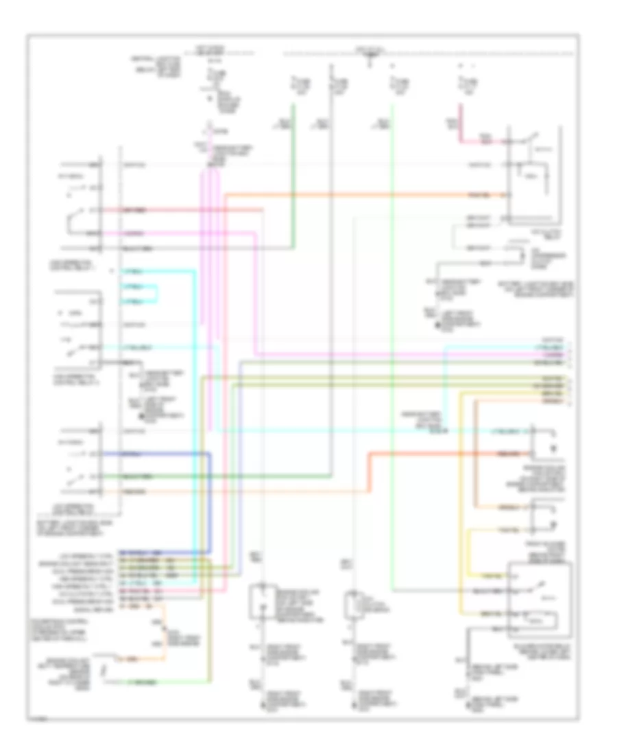
2.0L, Manual A/C Wiring Diagram (1 of 2) for Ford Escape 2001

List of elements for 2.0L, Manual A/C Wiring Diagram (1 of 2) for Ford Escape 2001:
- (behind left side dash panel) s221
- (left front side engine compartment) g100
- (left front side of engine compartment) g100
- (near battery junction box (bjb)) s127
- (near battery junction box (bjb)) s131 (or s132)
- (near battery junction box (bjb)) s132
- (near battery junction box (bjb)) s144
- (right front side engine compartment) g101
- (right front side engine compartment) s116
- A/c clutch relay
- A/c clutch rly ctrl
- A/c clutch solenoid
- A/c compressor clutch diode
- Battery junction box (bjb) (on left front corner of engine compartment)
- Blower motor relay (behind lower left center of dash)
- C270b
- C270c
- Central junction box (cjb) (below left end of dash)
- Cyl temp sensor input
- Cylinder head temperature sensor (on right front of cylinder head)
- Dual pressure sw sig
- Engine cooling fan motor 1 (on left side of engine compartment, behind radiator)
- Engine cooling fan motor 2 (on right side of engine compartment, behind radiator)
- Front blower motor (behind right side of dash)
- Fuse f1.17 15a
- Fuse f1.23 40a
- Fuse f1.25 40a
- Fuse f1.26 40a
- Fuse f2.2 5a
- Fuse f2.9 3a
- High speed fan control relay 1
- High speed rly ctrl 1
- Hot at all times
- Hot in run or start
- Low speed fan control relay
- Low speed rly ctrl
- Med speed rly ctrl
- Medium speed fan control relay
- Pcm module power diode
- Powertrain control module (pcm) (in recess on upper center of firewall)
- S100 (center rear engine)
- Signal return
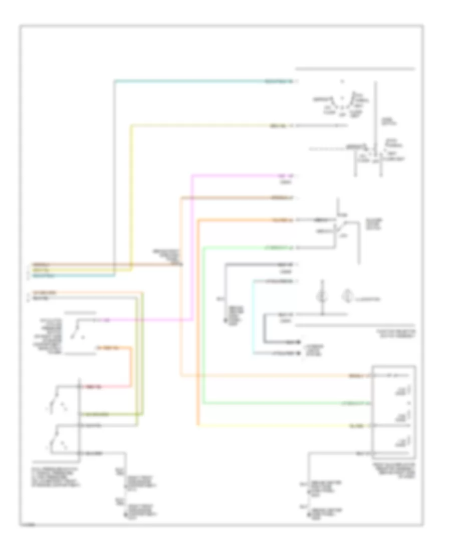
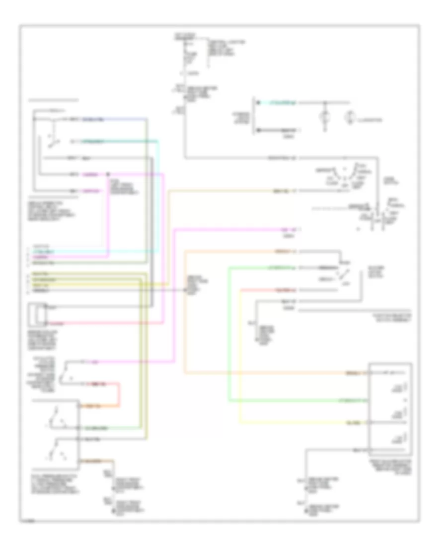
2.0L, Manual A/C Wiring Diagram (2 of 2) for Ford Escape 2001
List of elements for 2.0L, Manual A/C Wiring Diagram (2 of 2) for Ford Escape 2001:
- (behind center dash panel) g206
- (behind right side dash panel) s200
- (right front side engine compartment) g101
- (right front side engine compartment) s114
- 0.33 ohms
- 0.62 ohms
- 1.38 ohms
- A/c clutch cycling pressure switch (on right side of engine compartment, near strut tower)
- Blower motor switch
- C294a
- C294b
- C294c
- Defrost
- Dual pressure switch (1: normal pressure) (2: high pressure) (on lower right front of engine compartment)
- Floor
- Floor/ vent
- Floor/vent
- Front blower motor resistor assembly (behind right side of dash)
- Function selector switch assembly
- High
- Illumination
- Interior lights system
- Low
- Max
- Medium 1
- Medium 2
- Mix
- Mode switch
- Normal
- Off
- Right side dash panel) s203
- Vent
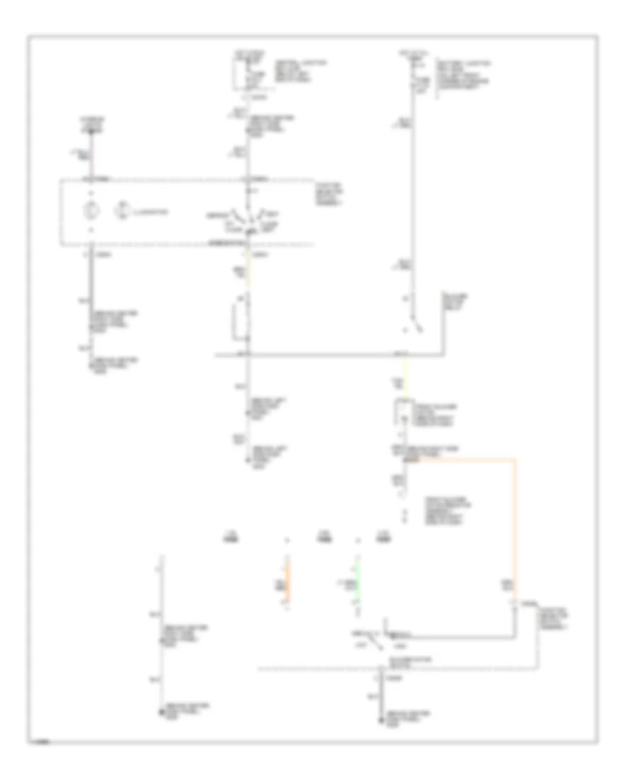
Heater Wiring Diagram for Ford Escape 2001
List of elements for Heater Wiring Diagram for Ford Escape 2001:
- (behind center dash panel) g206
- (behind center right side dash panel) s203
- (behind center right side, dash panel) s203
- (behind left side dash panel) g202
- (behind left side dash panel) s221
- 0.33 ohms
- 0.62 ohms
- 1.38 ohms
- Battery junction box (bjb) (on left front corner of engine compartment)
- Blower motor relay
- Blower motor switch
- C270c
- C294a
- C294b
- C294c
- Central junction box (cjb) (below left end of dash)
- Defrost
- Floor
- Floor/ vent
- Front blower motor (behind right side of dash)
- Front blower motor resistor assembly (behind right side of dash)
- Function selector switch assembly
- Fuse f1.23 40a
- Fuse f2.2 5a
- High
- Hot at all times
- Hot in run or start
- Illumination
- Interior lights system
- Low
- Medium 1
- Medium 2
- Mix
- Mode switch
- Off
- Vent
3.0L
3.0L, Manual A/C Wiring Diagram (1 of 2) for Ford Escape 2001
List of elements for 3.0L, Manual A/C Wiring Diagram (1 of 2) for Ford Escape 2001:
- (behind left side dash panel) s221
- (left front side engine compartment) g100
- (near battery junction box (bjb)) s128
- (near battery junction box (bjb)) s145
- (right front side engine compartment) g101
- (right front side engine compartment) s116
- 87a
- A/c clutch relay
- A/c clutch rly ctrl
- A/c clutch solenoid
- A/c compressor clutch diode
- Battery junction box (bjb) (on left front corner of engine compartment)
- Blower motor relay (behind lower left center of dash)
- C270b
- Central junction box (cjb) (below left end of dash)
- Dual pressure sw sig
- Engine coolant (ect) temperature sensor (on rear of right cylinder head)
- Engine coolant sens input
- Engine cooling fan motor 1 (on left side of engine compartment, behind radiator)
- Engine cooling fan motor 2 (on right side of engine compartment, behind radiator)
- Front blower motor (behind right side of dash)
- Fuse f1.17 15a
- Fuse f1.23 40a
- Fuse f1.25 40a
- Fuse f1.26 40a
- Fuse f2.9 3a
- High speed fan control relay 1
- High speed fan control relay 2
- High speed rly ctrl 1
- Hot at all times
- Hot in run or start
- Junction box (bjb)) s132
- Low speed fan control relay
- Low speed rly ctrl
- Med speed rly ctrl
- Pcm module power diode
- Powertrain control module (pcm) (in recess on upper center of firewall)
- Side of engine compartment) g100
- Signal return
3.0L, Manual A/C Wiring Diagram (2 of 2) for Ford Escape 2001
List of elements for 3.0L, Manual A/C Wiring Diagram (2 of 2) for Ford Escape 2001:
- (behind center dash panel) g206
- (behind right side dash panel) s200
- (right front side engine compartment) g101
- (right front side engine compartment) s114
- 0.33 ohms
- 0.62 ohms
- 1.38 ohms
- 87a
- A/c clutch cycling pressure switch (on right side of engine compartment, near strut tower)
- Blower motor switch
- C270c
- C294a
- C294b
- C294c
- Central junction box (cjb) (below left end of dash)
- Defrost
- Dual pressure switch (1: normal pressure) (2: high pressure) (on lower right front of engine compartment)
- Engine cooling fan resistor (on lower left side of engine compartment)
- Floor
- Floor/ vent
- Front blower motor resistor assembly (behind right side of dash)
- Function selector switch assembly
- Fuse f2.2 5a
- High
- Hot in run or start
- Illumination
- Interior lights system
- Low
- Max
- Medium 1
- Medium 2
- Medium speed fan control relay (on lower left front of engine compartment, near headlight)
- Mix
- Mode switch
- Normal
- Off
- Right side dash panel) s203
- S135 (left front side engine compartment)
- Vent
Heater Wiring Diagram for Ford Escape 2001
List of elements for Heater Wiring Diagram for Ford Escape 2001:
- (behind center dash panel) g206
- (behind center right side dash panel) s203
- (behind center right side, dash panel) s203
- (behind left side dash panel) g202
- (behind left side dash panel) s221
- 0.33 ohms
- 0.62 ohms
- 1.38 ohms
- Battery junction box (bjb) (on left front corner of engine compartment)
- Blower motor relay
- Blower motor switch
- C270c
- C294a
- C294b
- C294c
- Central junction box (cjb) (below left end of dash)
- Defrost
- Floor
- Floor/ vent
- Front blower motor (behind right side of dash)
- Front blower motor resistor assembly (behind right side of dash)
- Function selector switch assembly
- Fuse f1.23 40a
- Fuse f2.2 5a
- High
- Hot at all times
- Hot in run or start
- Illumination
- Interior lights system
- Low
- Medium 1
- Medium 2
- Mix
- Mode switch
- Off
- Vent