AIR CONDITIONING
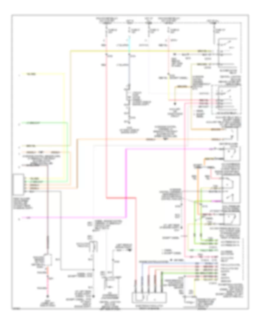
Automatic A/C Wiring Diagram (1 of 2) for Ford Excursion 2005

List of elements for Automatic A/C Wiring Diagram (1 of 2) for Ford Excursion 2005:
- (under left side of dash) g300
- A/c demand sig
- Air bag sliding contact (in steering column)
- Ambient air temperature sensor (on left front of engine compt)
- Ambient temp
- Batt
- Blend door actuator
- Blend door monitor
- Blend door sense +
- Blend door signal -
- Blow motor rly control
- Blower motor high
- Blower speed control signal return
- C1381a
- C218a
- C228a
- C228b
- C270a
- Central junction box (cjb) (behind lower left side of dash)
- Computer data lines system
- Cruise control system
- Diesel
- Electronic automatic temperature control (eatc) module (behind center of dash)
- Except diesel
- Fan speed (+)
- Fan speed (-)
- Fuse 10a
- Hot at all times
- Hot in run
- Ign
- Illumination
- In car temp sensor
- In-vehicle temperature sensor (behind left side of dash)
- Interior lights system
- Logic gnd
- Nca
- Powertrain control module (pcm) (left side of engine compt)
- Remote solenoid assembly (center of dash)
- Rest
- S191 (in main harness, near breakout for c146)
- S201
- S228
- Sensor return
- Sig rtn
- Solenoid assembly
- Speed control servo (in right side of engine compt)
- Speed controller
- Steering wheel controls
- Steering wheel radio switch
- Sunload sensor sig
- Temp (+)
- Temp (-)
- Temperature blend door actuator (behind right side of dash)
- Ubp diag
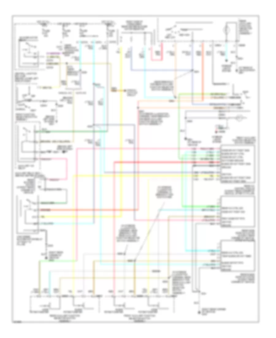
Automatic A/C Wiring Diagram (2 of 2) for Ford Excursion 2005
List of elements for Automatic A/C Wiring Diagram (2 of 2) for Ford Excursion 2005:
- (at left rear of eng compt) g100
- (at left rear of engine compt) g101
- (diesel)
- (diesel) (except diesel)
- (diesel: engine control harness, at breakout for auxiliary relay box 5) s171
- (except diesel)
- (in engine control harness, at breakout for front blower motor speed controller) s158
- (in engine control harness, near breakout for g100) s173
- (in engine control harness, near breakout for powertrain control module)
- (in engine control sensor harn, at breakout for front blower motor speed controller)
- (left rear of engine compt) g100
- (pcm power relay) hot in start or run
- A/c clutch field coil
- A/c clutch relay
- A/c compressor clutch diode
- A/c compressor cycling switch (in right rear of engine compartment, on a/c accumulator)
- A/c high pressure switch (5.4l: in right side of engine compt) (6.8l: lower right front of engine)
- A/c press sw in
- A/c press switch sig
- Auxiliary air conditioning circuit
- Auxiliary relay box 4 (except diesel) auxiliary relay box 5 (diesel) (at left rear side of engine compt)
- Blower motor relay
- C1381a
- C1381c
- C175
- C270a
- C270f
- C270g
- C270h
- Central junction box (cjb) (behind lower left side of dash)
- Diesel
- Dual pressure switch (diesel) (at right front of engine)
- Electronic fan clutch (front of engine)
- Engine controls system
- Engine coolant temperature (ect) sensor (front of engine)
- Except
- Except diesel
- Fan clutch ctrl
- Fan clutch sig
- Front blower motor speed controller (at right rear of engine compt)
- Fuse 10 10a
- Fuse 107 40a
- Fuse 22 20a
- Fuse 23 20a
- Fuse 27 15a
- G108 (at right side of engine compt)
- G202 (behind left side of dash)
- G300 (under left side of dash)
- Heater blower motor
- Hot at all times
- Hot in run
- Nca
- Powertrain control module (pcm) (diesel: left side of engine compt) (except diesel: on left side of firewall)
- Red
- S102 s180
- S106
- S116
- S124
- S157
- S162
- S180
- S192 (near breakout for manifold air temperature sensor)
- S193
- S201
- S218
- Sens sig
- Sig rtn
- Sunload sensor (on top center of dash)
- Vacuum pump motor (diesel) (in right side of engine compt)
- Vref
Auxiliary Heater-A/C Wiring Diagram for Ford Excursion 2005
List of elements for Auxiliary Heater-A/C Wiring Diagram for Ford Excursion 2005:
- (at rear of vehicle roof) g901
- (behind left side of dash) g201
- (behind left side of dash) g202
- (in interior illumination harness, in breakout for dvd player)
- (in interior illumination harness, near breakout for
- (in interior illumination harness, near breakout for rear auxiliary function selector switch assembly)
- (near breakout for rear auxiliary function selector switch assembly)
- (right rear corner of vehicle) g403
- (right side of cargo area) rear heater blower motor resistor
- 87a
- Auto a/c
- Auxiliary a/c relay
- Auxiliary relay box 1 (behind center of dash)
- Blend dr act ctrl
- Blend dr act posit sns
- Blend dr pot rtn
- Blend potentiometer
- Blower motor
- C270a
- C270d
- C270g
- C270j
- C294a
- C989a
- C989b
- C989c
- C989d
- C990a
- C990b
- C990c
- C990d
- Central junction box (cjb) (behind lower left side of dash)
- Def
- Floor
- Frnt mode pot rtn
- Front auxiliary function selector switch assembly
- Front function selector switch assembly
- Fuse 10a
- Fuse 15a
- Fuse 40a
- G901 (at rear of vehicle)
- Ground
- High
- High speed blower motor relay (at right "d" pillar)
- Hot at all times
- Hot in run
- Ignition
- Interior lights system
- Low
- Manual a/c
- Manual/ auto a/c circuit
- Max
- Med high
- Med low
- Mix
- Mode act posit sig
- Mode act posit sns
- Mode dr act ctrl
- Mode dr act posit sns
- Mode potentiometer
- Normal
- Off
- Rear a/c control module (in right rear corner of vehicle, after "c" pillar)
- Rear a/c ctrl sig
- Rear auxiliary function
- Rear auxiliary function selector switch assembly
- Rear blend door actuator (in right rear corner of vehicle)
- Rear blower motor (in right rear corner of vehicle)
- Rear mode door actuator (in right rear corner of vehicle, after "c" pillar)
- Red
- Red/ pnk
- Relay
- S173 (near breakout for g100)
- S206
- S217
- S290
- S320
- S321
- S322
- S323
- S924
- S925
- S927 (in interior illumination harness, near breakout for rear auxiliary function selector switch assembly)
- S928
- S929
- S930
- S931
- S934
- S935
- Selector switch assembly)
- Switched ground
- Temp blend dr act feed
- Vent
Manual A/C Wiring Diagram for Ford Excursion 2005
List of elements for Manual A/C Wiring Diagram for Ford Excursion 2005:
- (at left rear of engine compt) g100
- (at left rear side of engine compt) g100
- (at right side of engine compt) g108
- (behind left side of dash) g201
- (diesel)
- (except diesel)
- (except diesel) (diesel)
- (except diesel) s122
- (in engine control harness, near breakout for powertrain control module)
- (in engine control sensor harness, at breakout for front heater blower motor resistor) s152
- (left rear of engine compt) g101
- (near breakout for manifold air temperature sensor) s192
- (pcm power relay) hot in start or run
- A/c clutch field coil
- A/c clutch relay
- A/c compressor clutch diode
- A/c compressor cycling switch (in right rear of engine compartment, on a/c accumulator)
- A/c high pressure switch (5.4l: in right side of engine compt) (6.8l: lower right front of engine)
- A/c press sw in
- A/c press switch sig rtn
- Auxiliary air conditioning circuit
- Auxiliary relay box 4 (except diesel) auxiliary relay box 5 (diesel) (at left rear side of engine compt)
- Blower motor relay
- Blower motor switch
- C1381a
- C1381c
- C175
- C270a
- C270f
- C270g
- C270h
- C294a
- C294b
- C294c
- C294d
- Central junction box (cjb) (behind lower left side of dash)
- Cooling fan speed sig
- Defrost
- Diesel
- Dual pressure switch (diesel) (at right front of engine)
- Electronic fan clutch (diesel) (front of engine)
- Electronic fan clutch ctrl
- Engine controls system
- Engine coolant temperature (ect) sensor (on top left front of engine)
- Except
- Except diesel
- Floor
- Front function selector switch assembly
- Front heater blower motor resistor (right rear of engine compt)
- Fuse 10 10a
- Fuse 10a
- Fuse 23 20a
- Fuse 27 15a
- Fuse 40a
- G108 (at right side of engine compt)
- Heater blower motor
- High
- Hot at all times
- Hot in run
- Illumination
- Interior lights system
- Low
- Max
- Med
- Mix
- Mode switch
- Nca
- Normal
- Of engine compartment) g108
- Off
- Powertrain control module (pcm) (diesel: left side of engine compt) (exc diesel: on left side of firewall)
- Powertrain control module (pcm) (diesel: left side of engine compt) (except diesel: on left side of firewall)
- Red
- S106
- S116
- S124
- S162
- S173 (in engine control harness, near breakout for g100)
- S180
- S180 s102
- S193
- S235
- S257
- S290
- Sig rtn
- Solid state
- Temperature blend door actuator (behind right side of dash)
- Temperature control potentiometer
- Vacuum pump motor (diesel) (in right side of engine compt)
- Vent
- Vref