AIR CONDITIONING
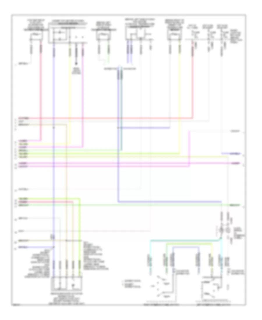
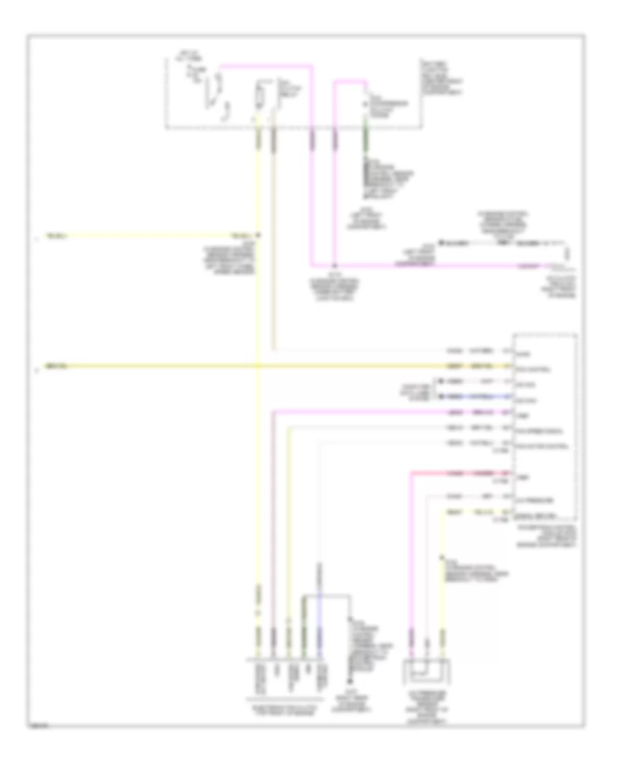
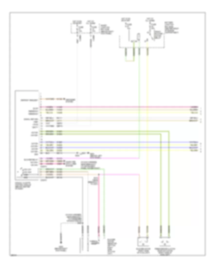
Automatic A/C Wiring Diagram, with Auxiliary Climate Control (1 of 3) for Ford Expedition 2007

List of elements for Automatic A/C Wiring Diagram, with Auxiliary Climate Control (1 of 3) for Ford Expedition 2007:
- (bottom left side of hvac unit) driver temperature blend door actuator
- (in console panel harness, near to satellite radio receiver) s349
- (in front heater blower motor harness, near breakout to c299) s217
- (left side of hvac unit) mode door actuator
- (near breakout to driver temperature blend door actuator) s220
- (near breakout to glove box light)
- (near breakout to instrument panel power point)
- (near breakout to passenger air bag module) s227
- (on left "b" pillar) g301
- (right side of hvac unit) fresh/ recirculation door actuator
- Ambient signal
- Battery junction box (bjb) (center front of engine compartment)
- Blower
- Blower motor (right side of hvac unit)
- Blower relay
- C228a
- C228b
- Cbp37
- Ch112
- Ch113
- Ch114
- Ch122
- Ch123
- Ch202
- Ch203
- Ch207
- Ch208
- Ch212
- Ch213
- Ch228
- Ch229
- Ch233
- Ch234
- Ch238
- Ch239
- Ch402
- Ch447
- Computer data lines system
- Defogger system
- Defrost request
- Driver sunload
- Electronic automatic temperature control (eatc) module (in center of dash)
- Evap
- Except expedition el
- Expedition el
- Feedback
- Front blower motor relay
- Fuse 10a
- Fuse 40a
- G200 (behind right kick panel)
- G203 (behind left kick panel)
- Gd113
- Gd138
- Gnd
- Heater blower motor control module (right side of hvac unit)
- Hot at all times
- Hot in on or start
- Humidity signal
- In-vehicle signal
- Interior lights system
- Lh111
- Lh115
- Mode/temp
- Motor+
- Motor-
- Ms can+
- Ms can-
- Passenger sunload
- Passenger temperature blend door actuator (top front of hvac unit)
- Rear auxiliary function switch assembly
- Rear mode door actuator (expedition el: left side of hvac unit) (except expedition el: top left side of hvac unit)
- Redundant cc signal
- Relay 1
- Relay 2
- Relay 3
- Rh111
- S219 (near breakout to passenger temperature blend door actuator)
- S222
- S223
- S228
- Sbp15
- Signal return
- Variable blower control
- Vbatt
- Vdb06
- Vdb07
- Vh101
- Vh301
- Vh406
- Vh407
- Vh413
- Vh414
- Vh416
- Vh417
- Vh436
- Vh438
- Vh439
- Vh440
- Vh441
- Vha15
- Vha17
- Vpwr
- Vref
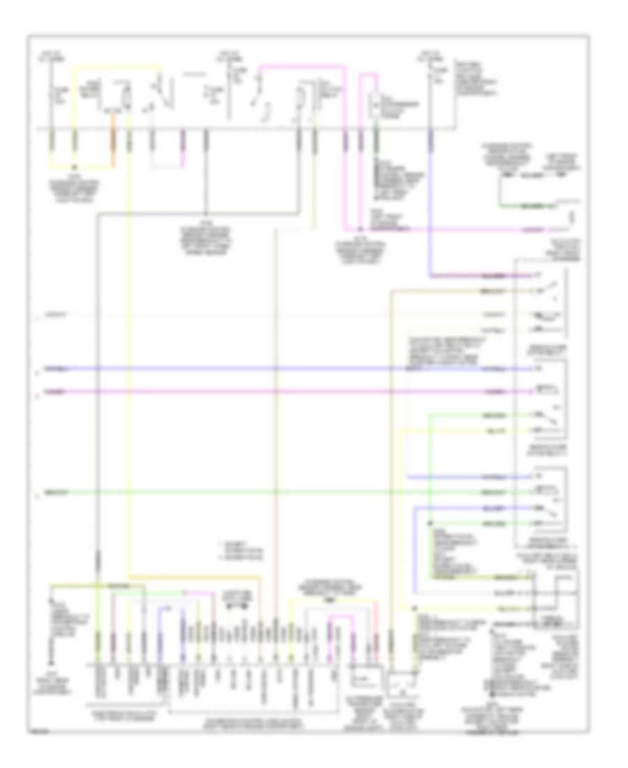
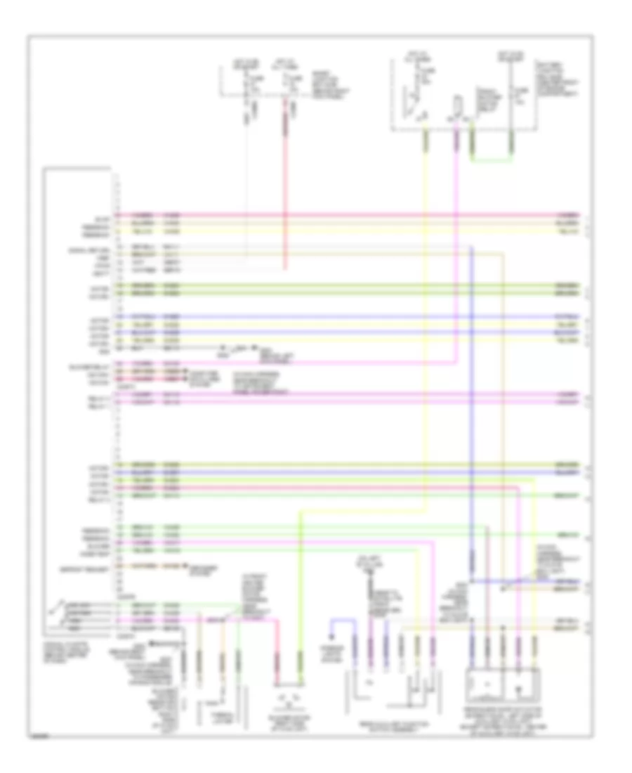
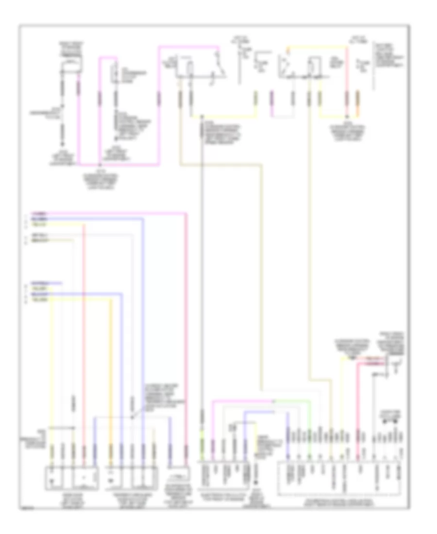
Automatic A/C Wiring Diagram, with Auxiliary Climate Control (2 of 3) for Ford Expedition 2007
List of elements for Automatic A/C Wiring Diagram, with Auxiliary Climate Control (2 of 3) for Ford Expedition 2007:
- (behind front of radiator grille) ambient air temperature sensor
- (behind left side of dash) (navigator) in-vehicle temperature/ humidity sensor
- (behind left side of dash) in-vehicle temperature sensor
- (top center of hvac unit) evaporator discharge air temperature sensor
- (under top center of dash) sunload sensor
- C218a
- C218b
- C2280e
- C2280f
- C2280g
- Clock spring (in steering wheel)
- Except expedition el
- Expedition
- Expedition el
- Fan+
- Fan-
- Fuse 10a
- Fuse 7.5a
- Head- lights system
- Hot at all times
- Hot in on or start
- Left steering wheel switch
- Navigator
- Rear blend door actuator (expedition el: left side of hvac unit) (except expedition el: center of auxiliary hvac unit)
- Right steering wheel switch
- S410 (except expedition el) (in breakout to rear mode door actuator) s430 (expedition el) (in auxiliary case jumper, near breakout to rear mode door actuator)
- S411 (except expedition el) (in breakout to rear mode door actuator) s429 (expedition el) (in auxiliary case jumper, near breakout to rear mode door actuator)
- Smart junction box (sjb) (behind right kick panel)
- Solid state
- Temp+
- Temp-
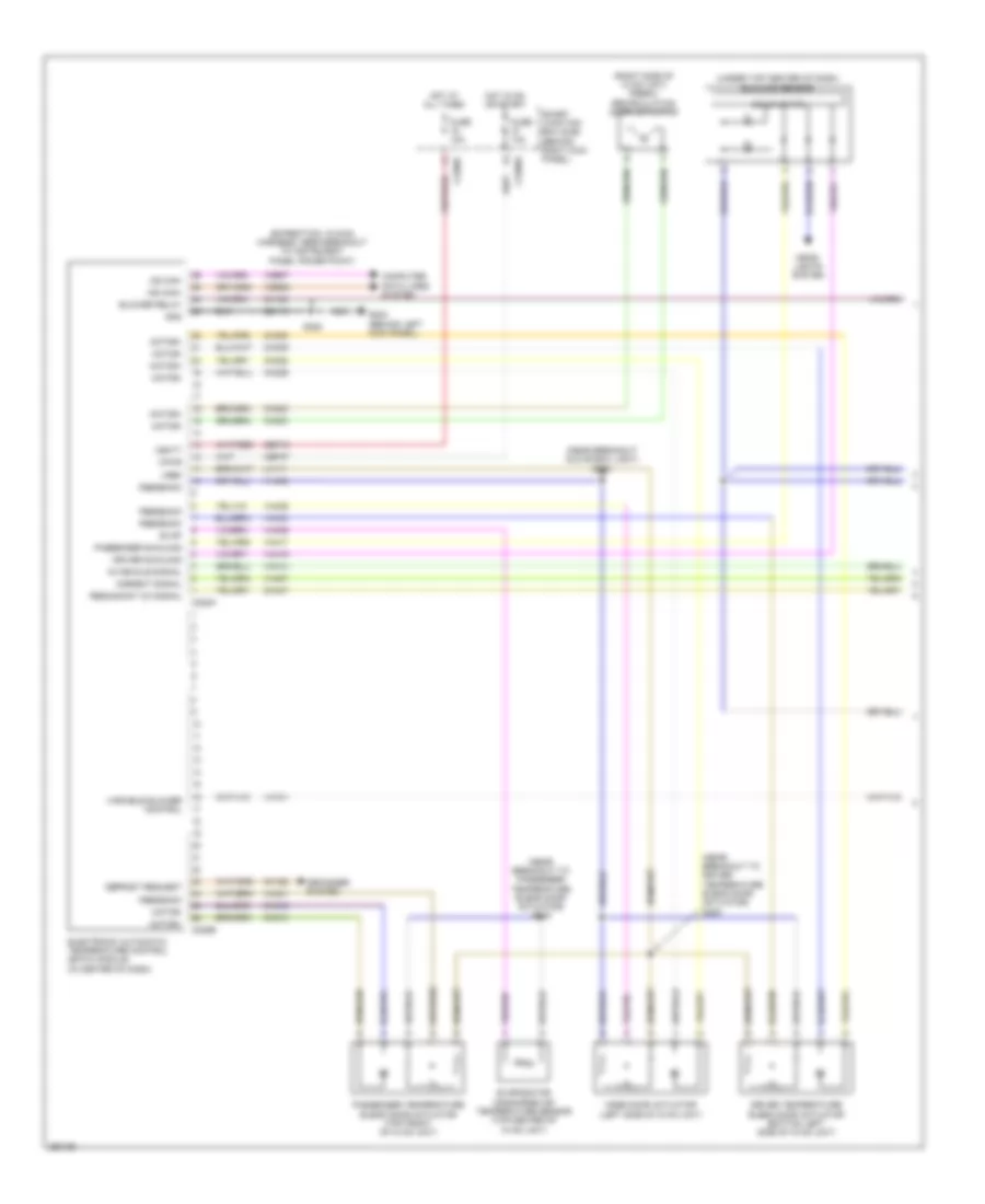
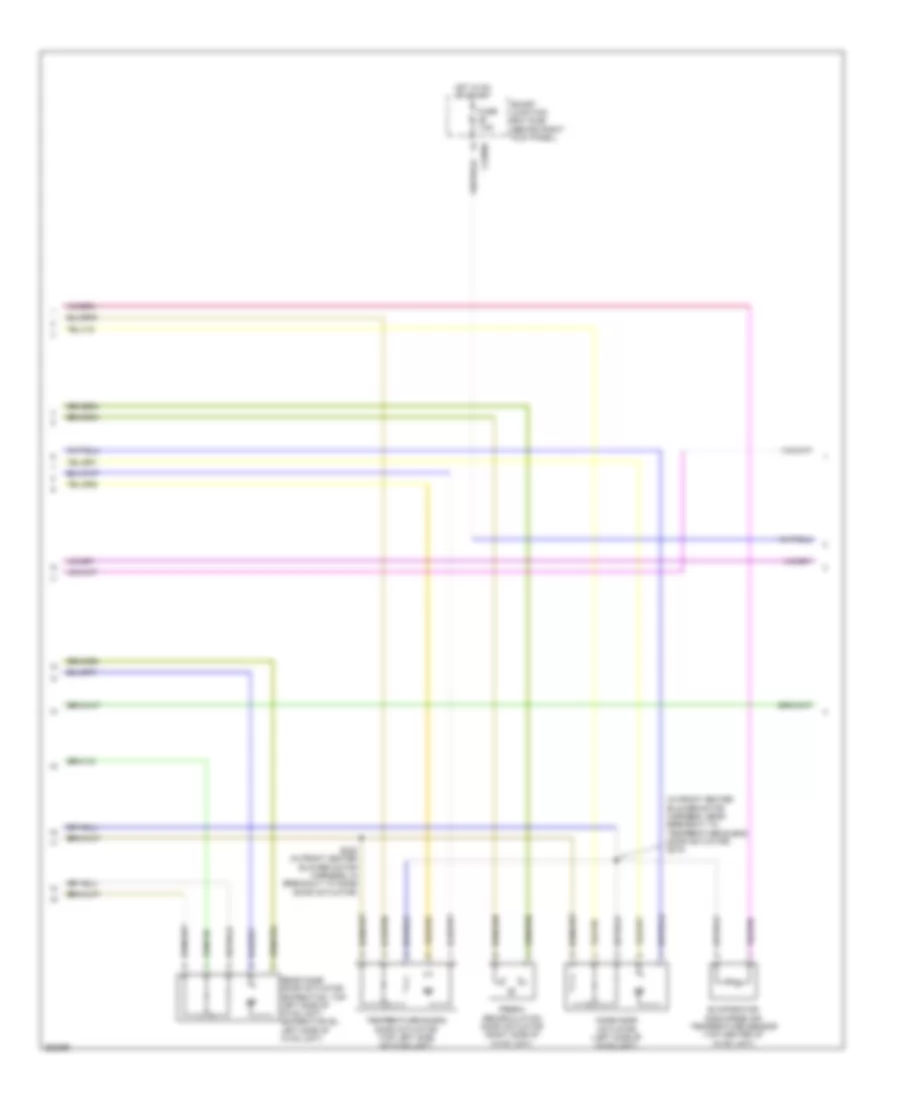
Automatic A/C Wiring Diagram, with Auxiliary Climate Control (3 of 3) for Ford Expedition 2007
List of elements for Automatic A/C Wiring Diagram, with Auxiliary Climate Control (3 of 3) for Ford Expedition 2007:
- (in engine control sensor & fuel charge harness, near breakout to c145) s140
- (in engine control sensor harness, near breakout to horn) s122
- (left front of engine compartment) g103
- (navigator: near breakout to auxiliary relay box 2) (except navigator: breakout to right rear quarter window motor) s417
- (near breakout to powertrain control module)
- (right rear of engine compartment)
- A/c clutch field coil (right front of engine)
- A/c clutch relay
- A/c compressor clutch diode
- A/c pressure
- A/c pressure transducer sensor (right front of engine compt)
- Accr
- Auxiliary blower motor (right side of auxiliary hvac unit)
- Auxiliary blower motor resistor assembly (right side of auxiliary hvac unit)
- Auxiliary relay box 2 (right rear corner of vehicle)
- Battery junction box (bjb) (center front of engine compartment)
- C175b
- C175e
- Ce607
- Ch302
- Ch421
- Computer data lines system
- Control fan motor
- Electronic fan clutch (top front of engine)
- Except expedition el
- Expedition el
- Fan motor control
- Fan speed signal
- Fuse 10a
- Fuse 20a
- Fuse 30a
- G103 (left front of engine compartment)
- G107
- G403 (navigator: left rear corner of vehicle) (except navigator: right rear corner of vehicle)
- Gnd
- Hot at all times
- Hs can+
- Hs can-
- Le423
- Pcm control
- Pcm power relay
- Pcm power rly sw out
- Powertrain control module (pcm) (right rear of engine compartment)
- Re407
- Rear blower motor relay 1
- Rear blower motor relay 2
- Rear blower motor relay 3
- S102
- S106 (in engine control sensor harness, near breakout to left front wheel speed sensor)
- S119 (in engine control sensor harness, under battery junction box)
- S120 (in engine control sensor harness, under battery junction box)
- S418 (w/ power vent windows) (navigator: breakout to g402) (except navigator: near breakout right rear quarter window motor)
- S422 (expedition el) (near breakout to c408) s414 (except expedition el) (near breakout to g402)
- S428 (near breakout to rear mode door actuator) s412 (near breakout to auxiliary blower motor resistor assembly)
- Signal return
- Thermal limiter
- Vdb04
- Vdb05
- Vec03
- Vec10
- Vh433
- Vref
Automatic A/C Wiring Diagram, without Auxiliary Climate Control (1 of 3) for Ford Expedition 2007
List of elements for Automatic A/C Wiring Diagram, without Auxiliary Climate Control (1 of 3) for Ford Expedition 2007:
- (expedition: in main harness, near breakout to instrument panel power point)
- (near breakout glove box light) s223
- (near breakout to driver temperature blend door actuator) s220
- (near breakout to passenger temperature blend door actuator) s219
- (right side of hvac unit) fresh/ recirculation door actuator
- (under top center of dash) sunload sensor
- Ambient signal
- Blower relay
- C2280f
- C2280g
- C228a
- C228b
- Cbp37
- Ch122
- Ch123
- Ch202
- Ch203
- Ch212
- Ch213
- Ch228
- Ch229
- Ch238
- Ch239
- Ch447
- Computer data lines system
- Defogger system
- Defrost request
- Driver sunload
- Driver temperature blend door actuator (bottom left side of hvac unit)
- Electronic automatic temperature control (eatc) module (in center of dash)
- Evap
- Evaporator discharge air temperature sensor (top center of hvac unit)
- Feedback
- Fuse 10a
- G203 (behind left kick panel)
- Gd113
- Gnd
- Head- lights system
- Hot at all times
- Hot in on or start
- In-vehicle signal
- Lh111
- Mode door actuator (left side of hvac unit)
- Motor+
- Motor-
- Ms can+
- Ms can-
- Passenger sunload
- Passenger temperature blend door actuator (top front of hvac unit)
- Redundant cc signal
- S228
- Sbp15
- Smart junction box (sjb) (behind right kick panel)
- Solid state
- Variable blower control
- Vbatt
- Vdb06
- Vdb07
- Vh101
- Vh406
- Vh407
- Vh414
- Vh416
- Vh417
- Vh436
- Vh440
- Vh441
- Vpwr
- Vref
Automatic A/C Wiring Diagram, without Auxiliary Climate Control (2 of 3) for Ford Expedition 2007
List of elements for Automatic A/C Wiring Diagram, without Auxiliary Climate Control (2 of 3) for Ford Expedition 2007:
- (behind front of radiator grille) ambient air temperature sensor
- (behind left side of dash) in-vehicle temperature sensor
- (in front heater blower motor harness, near breakout to c299) s217
- (in main harness, near breakout to passenger air bag module) s227
- Battery junction box (bjb) (center front of engine compartment)
- Blower motor (right side of hvac unit)
- C218a
- C218b
- Ch402
- Clock spring (in steering wheel)
- Fan+
- Fan-
- Front blower motor relay
- Fuse 10a
- Fuse 20a
- Fuse 30a
- Fuse 40a
- G200 (behind right kick panel)
- Gd138
- Heater blower motor control module (right side of hvac unit)
- Hot at all times
- Hot in on or start
- Left steering wheel switch
- Pcm power relay
- Right steering wheel switch
- S120 (in engine control sensor harness, under battery junction box)
- Temp+
- Temp-
- Vh101
- Vh301
Automatic A/C Wiring Diagram, without Auxiliary Climate Control (3 of 3) for Ford Expedition 2007
List of elements for Automatic A/C Wiring Diagram, without Auxiliary Climate Control (3 of 3) for Ford Expedition 2007:
- (in engine control sensor & fuel charge harness, near breakout to c145) s140
- (right rear of engine compartment)
- A/c clutch field coil (right front of engine)
- A/c clutch relay
- A/c compressor clutch diode
- A/c pressure
- A/c pressure transducer sensor (right front of engine compartment)
- Accr
- Battery junction box (bjb) (center front of engine compartment)
- C175b
- C175e
- Ce607
- Ch302
- Ch421
- Computer data lines system
- Control fan motor
- Electronic fan clutch (top front of engine)
- Fan motor control
- Fan speed signal
- Fuse 10a
- G103 (left front of engine compartment)
- G107
- Gnd
- Hot at all times
- Hs can+
- Hs can-
- Le423
- Pcm control
- Pcm power rly sw out
- Powertrain control module (pcm) (right rear of engine compartment)
- Re407
- S102 (in engine control sensor harness, near breakout to powertrain control module)
- S106 (in engine control sensor harness, near breakout to left front wheel speed sensor)
- S119 (in engine control sensor harness, under battery junction box)
- S122 (in engine control sensor harness, near breakout to horn)
- Signal return
- Vdb04
- Vdb05
- Vec03
- Vec10
- Vh433
- Vref
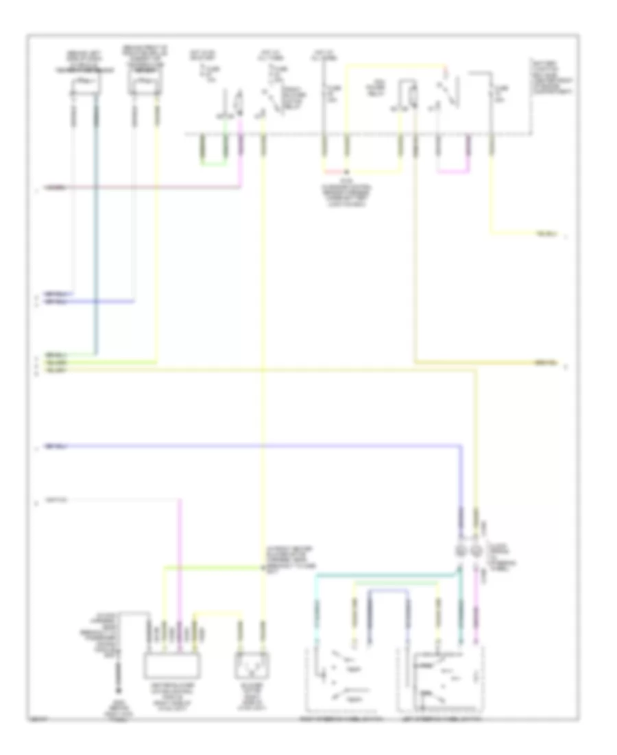
Manual A/C Wiring Diagram, with Auxiliary Climate Control (1 of 3) for Ford Expedition 2007
List of elements for Manual A/C Wiring Diagram, with Auxiliary Climate Control (1 of 3) for Ford Expedition 2007:
- (in front heater blower motor harness, near breakout to c237)
- (in main harness, near breakout to glove box light) s222
- (in main harness, near breakout to instrument panel power point)
- (near to satellite radio receiver) s349
- (on left "b" pillar) g301
- Battery junction box (bjb) (center front of engine compartment)
- Blower
- Blower motor (right side of hvac unit)
- Blower motor resistor (bottom right side of hvac unit)
- Blower relay
- C2280f
- C2280g
- C2357a
- C2357b
- C2357c
- Cbp37
- Ch112
- Ch113
- Ch114
- Ch122
- Ch123
- Ch202
- Ch203
- Ch207
- Ch208
- Ch228
- Ch229
- Ch233
- Ch234
- Ch238
- Ch239
- Ch428
- Ch429
- Ch430
- Computer data lines system
- Defogger system
- Defrost request
- Evap
- Feedback
- Front blower motor relay
- Fuse 10a
- Fuse 40a
- G200 (behind right kick panel)
- G203 (behind left kick panel)
- Gd113
- Gd138
- Gnd
- High
- Hot at all times
- Hot in on or start
- Interior lights system
- Lh111
- Manual climate control module (behind center of dash)
- Mid high
- Mid low
- Mode/temp
- Motor+
- Motor-
- Ms can+
- Ms can-
- Rear auxiliary function switch assembly
- Rear blend door actuator (expedition el: left side of auxiliary hvac unit) (except expedition el: center of auxiliary hvac unit)
- Relay 1
- Relay 2
- Relay 3
- Rh111
- S218
- S223 (in main harness, near breakout to glove box light)
- S227 (in main harness, near breakout to passenger air bag module)
- S228
- Sbp15
- Signal return
- Smart junction box (sjb) (behind right kick panel)
- Thermal limiter
- Vbatt
- Vdb06
- Vdb07
- Vh406
- Vh436
- Vh438
- Vh439
- Vh440
- Vha15
- Vha17
- Vpwr
- Vref
Manual A/C Wiring Diagram, with Auxiliary Climate Control (2 of 3) for Ford Expedition 2007
List of elements for Manual A/C Wiring Diagram, with Auxiliary Climate Control (2 of 3) for Ford Expedition 2007:
- (in front heater blower motor harness, near breakout to temperature blend door actuator) s219
- C2280e
- Evaporator discharge air temperature sensor (top center of hvac unit)
- Fresh/ recirculation door actuator (right side of hvac unit)
- Fuse 7.5a
- Hot in on or start
- Mode door actuator (left side of hvac unit)
- Rear mode door actuator (expedition: top left side of hvac unit) (expedition el: left side of hvac unit)
- S220 (in front heater blower motor harness, in breakout to mode door actuator)
- Smart junction box (sjb) (behind right kick panel)
- Temperature blend door actuator (top left side of hvac unit)
Manual A/C Wiring Diagram, with Auxiliary Climate Control (3 of 3) for Ford Expedition 2007
List of elements for Manual A/C Wiring Diagram, with Auxiliary Climate Control (3 of 3) for Ford Expedition 2007:
- (in engine control sensor & fuel charge harness, near breakout to c145) s140
- (in engine control sensor harness, near breakout to horn) s122
- (left front of engine compartment) g103
- (near breakout to right rear quarter window motor) s417
- (right rear corner of vehicle)
- (right rear of engine compartment)
- A/c clutch field coil (right front of engine)
- A/c clutch relay
- A/c compressor clutch diode
- A/c pressure
- A/c pressure transducer sensor (right front of engine compartment)
- Accr
- Auxiliary blower motor (right side of auxiliary hvac unit)
- Auxiliary blower motor resistor assembly (right side of auxiliary hvac unit)
- Auxiliary relay box 2 (right rear corner of vehicle)
- Battery junction box (bjb) (center front of engine compartment)
- C175b
- C175e
- Ce607
- Ch302
- Ch421
- Computer data lines system
- Control
- Control fan motor
- Electronic fan clutch (top front of engine)
- Fan motor
- Fan speed
- Fuse 10a
- Fuse 20a
- Fuse 30a
- G103 (left front of engine compartment)
- G107
- G403
- Gnd
- Hot at all times
- Hs can+
- Hs can-
- Le423
- Pcm control
- Pcm power relay
- Pcm power rly sw out
- Powertrain control module (pcm) (right rear of engine compartment)
- Re407
- Rear blower motor relay 1
- Rear blower motor relay 2
- Rear blower motor relay 3
- S102 (near breakout to powertrain control module)
- S106 (in engine control sensor harness, near breakout to left front wheel speed sensor)
- S119 (in engine control sensor harness, under battery junction box)
- S120 (in engine control sensor harness, under battery junction box)
- S412 (near breakout to auxiliary blower motor resistor assembly)
- S414 (in rear light connector harness, near breakout to g402)
- S418 (w/ power vent windows) (near breakout to right rear quarter window motor)
- Signal
- Signal fan speed
- Signal return
- Thermal limiter
- Vdb04
- Vdb05
- Vec03
- Vec10
- Vh433
- Vref
Manual A/C Wiring Diagram, without Auxiliary Climate Control (1 of 2) for Ford Expedition 2007
List of elements for Manual A/C Wiring Diagram, without Auxiliary Climate Control (1 of 2) for Ford Expedition 2007:
- (in main harness, near breakout to instrument panel power point)
- (in main harness, near breakout to passenger air bag module) s227
- Battery junction box (bjb) (center front of engine compartment)
- Blower motor (right side of hvac unit)
- Blower motor resistor (bottom right side of hvac unit)
- Blower relay
- C2280f
- C2280g
- C2357a
- C2357c
- Cbp37
- Ch122
- Ch123
- Ch202
- Ch203
- Ch228
- Ch229
- Ch238
- Ch239
- Ch428
- Ch429
- Ch430
- Computer data lines system
- Defogger system
- Defrost request
- Evap
- Feedback
- Fresh/recirculation door actuator (right side of hvac unit)
- Front blower motor relay
- Fuse 10a
- Fuse 40a
- G200 (behind right kick panel)
- G203 (behind left kick panel)
- Gd113
- Gd138
- Gnd
- High
- Hot at all times
- Hot in on or start
- Lh111
- Manual climate control module (behind center of dash)
- Mid high
- Mid low
- Motor+
- Motor-
- Ms can+
- Ms can-
- Rh111
- S218 (near breakout to c237)
- S228
- Sbp15
- Signal return
- Smart junction box (sjb) (behind right kick panel)
- Thermal limiter
- Vbatt
- Vdb06
- Vdb07
- Vh406
- Vh436
- Vh440
- Vpwr
- Vref
Manual A/C Wiring Diagram, without Auxiliary Climate Control (2 of 2) for Ford Expedition 2007
List of elements for Manual A/C Wiring Diagram, without Auxiliary Climate Control (2 of 2) for Ford Expedition 2007:
- (in engine control sensor harness, near breakout to horn) s122
- (in front heater blower motor harness, near breakout to temperature blend door actuator) s219
- (near breakout to powertrain control module) s102
- (right front of engine compartment) a/c pressure transducer sensor
- (right front of engine) a/c clutch field coil
- (right rear of engine compartment)
- A/c
- A/c compressor clutch diode
- A/c pressure
- Accr
- Battery junction box (bjb) (center front of engine compartment)
- C175b
- C175e
- Ce607
- Ch302
- Ch421
- Clutch
- Computer data lines system
- Control fan motor
- Electronic fan clutch (top front of engine)
- Evaporator discharge air temperature sensor (top center of hvac unit)
- Fuse 10a
- Fuse 20a
- Fuse 30a
- G103 (left front of engine compartment)
- G107
- Gnd
- Hot at all times
- Hs can+
- Hs can-
- Le423
- Mode door actuator (left side of hvac unit)
- Pcm
- Pcm control
- Pcm power rly sw out
- Power relay
- Powertrain control module (pcm) (right rear of engine compartment)
- Re407
- Relay
- S106 (in engine control sensor harness, near breakout to left front wheel speed sensor)
- S119 (in engine control sensor harness, under battery junction box)
- S120 (in engine control sensor harness, under battery junction box)
- S123 (in engine control sensor harness, near breakout to left front foglight)
- S140 (near breakout to c145)
- S220 (in breakout to mode door actuator)
- Signal fan speed
- Signal return
- Temperature blend door actuator (top left side of hvac unit)
- Vdb04
- Vdb05
- Vec03
- Vec10
- Vh433
- Vref