AIR CONDITIONING
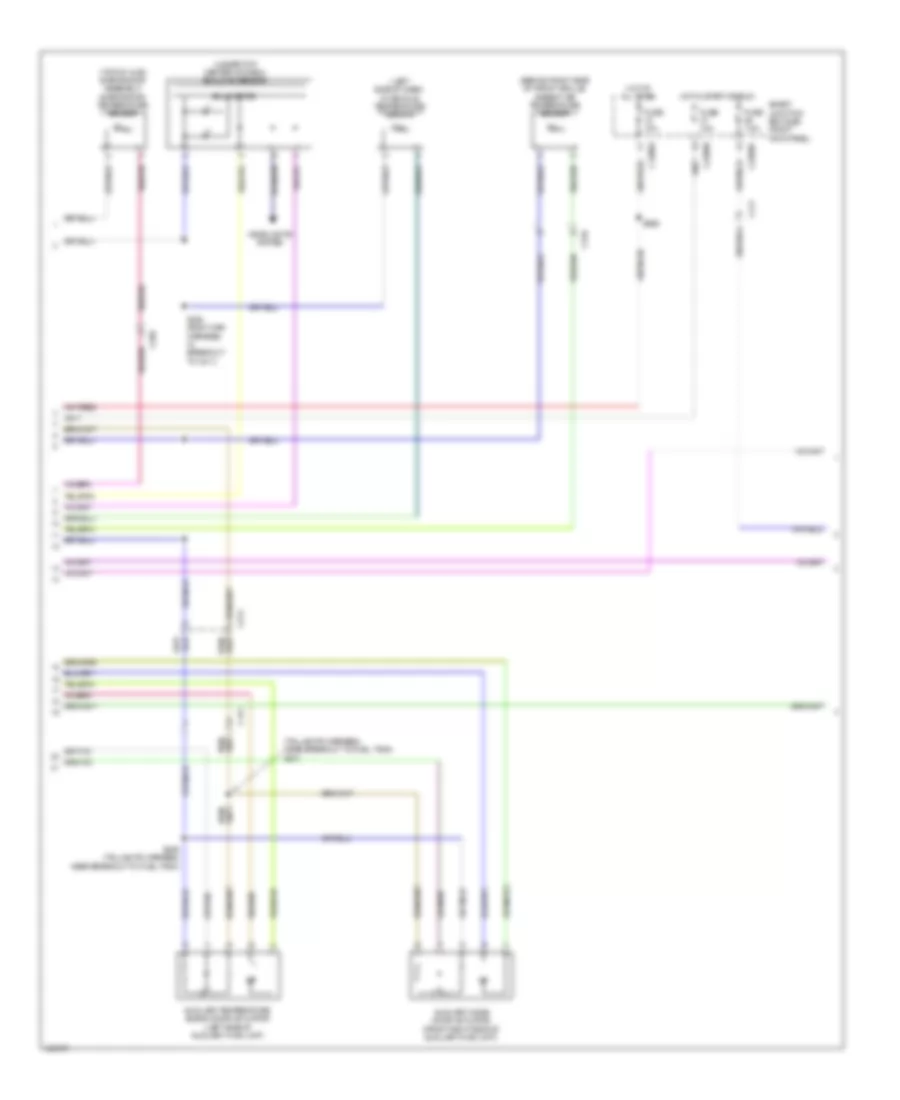
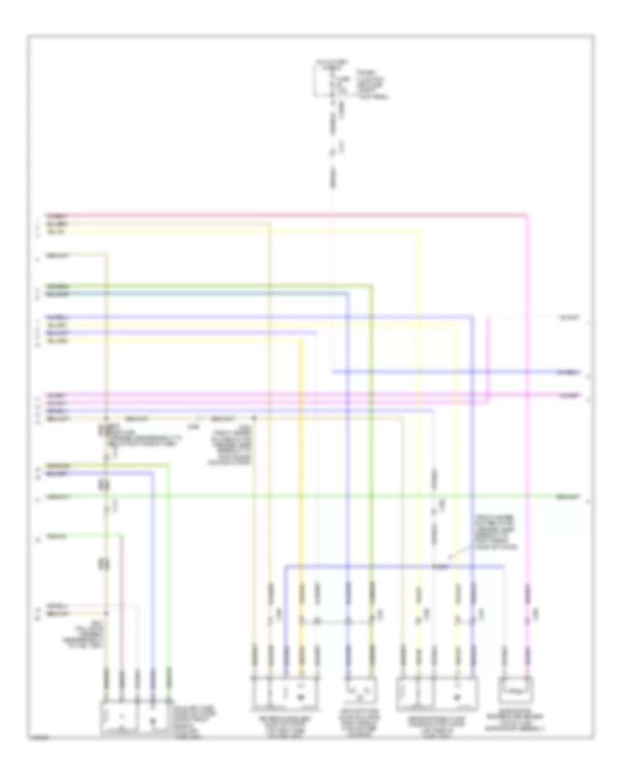
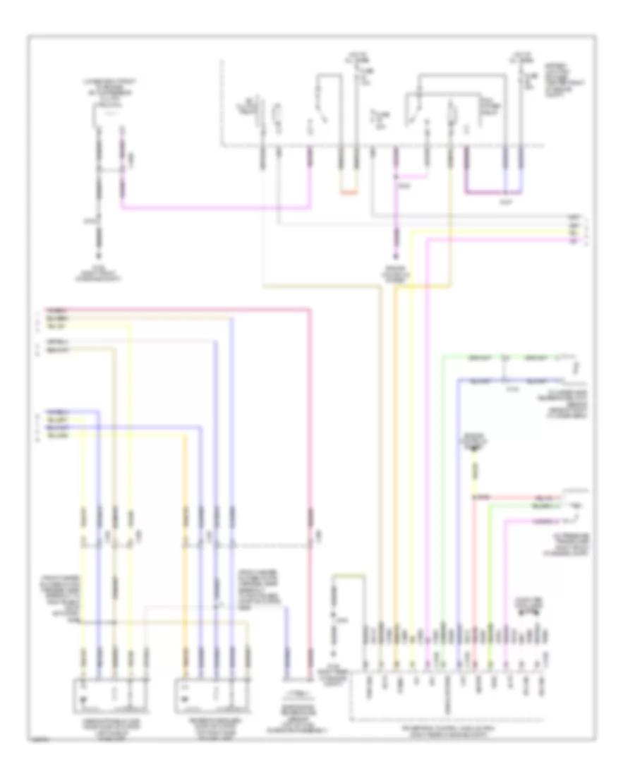
Automatic A/C Wiring Diagram, with Auxiliary Climate Control (1 of 4) for Ford Expedition EL XL 2014

List of elements for Automatic A/C Wiring Diagram, with Auxiliary Climate Control (1 of 4) for Ford Expedition EL XL 2014:
- (body main harness, near breakout to below right side of dash)
- (front heater blower motor harness, near breakout to right blend door actuator)
- (left side of hvac unit) defrost/panel/floor/ mode door actuator
- (lower center of hvac unit) left temperature blend door actuator (eatc)
- (right side of hvac blower housing) air inlet mode door actuator (eatc)
- Ambient signal
- Battery junction box (bjb) (center front of engine compt)
- Blower
- Blower motor (bottom right side of hvac unit)
- Blower motor relay
- Blower motor speed control (right side of hvac unit)
- Blower relay
- C210
- C214
- C228a
- C228b
- C238
- C291
- C299
- C315
- C411
- Cbp37
- Ch112
- Ch113
- Ch114
- Ch122
- Ch123
- Ch202
- Ch203
- Ch207
- Ch208
- Ch212
- Ch213
- Ch228
- Ch229
- Ch233
- Ch234
- Ch238
- Ch239
- Ch402
- Computer data lines system
- Defogger system
- Defrost request
- Driver sunload
- Evap
- Expedition
- Feedback
- Fuse 10a
- Fuse 40a
- G203 (left kick panel)
- G204 (right kick panel)
- G301 (left "b" pillar)
- Gd133
- Gd138
- Gnd
- Hot at all times
- Hot in start or run
- Hvac (datc) module
- In-vehicle signal
- Interior lights system
- Lh111
- Mode/temp
- Motor+
- Motor-
- Ms can+
- Ms can-
- Navigator
- Passenger sunload
- Rear auxiliary climate control assembly
- Relay 1
- Relay 2
- Relay 3
- Rh111
- Right temperature blend door actuator (upper center of hvac unit)
- S205
- S211
- S253
- S254
- S255 (front heater blower motor harness, near breakout to right blend door actuator)
- S369
- Sbp15
- Signal return
- Variable blower control
- Vbatt
- Vdb06
- Vdb07
- Vh101
- Vh301
- Vh406
- Vh407
- Vh414
- Vh416
- Vh417
- Vh436
- Vh438
- Vh439
- Vh440
- Vh441
- Vha15
- Vha17
- Vpwr
- Vref
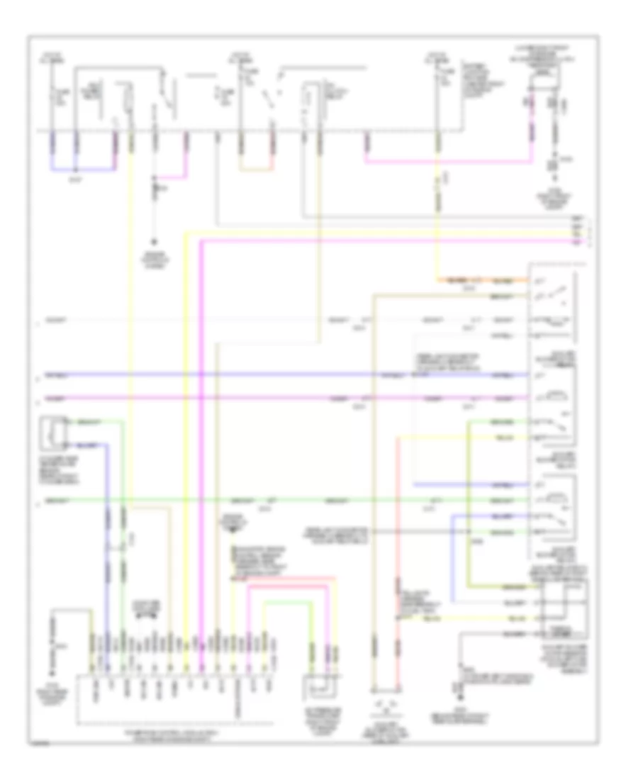
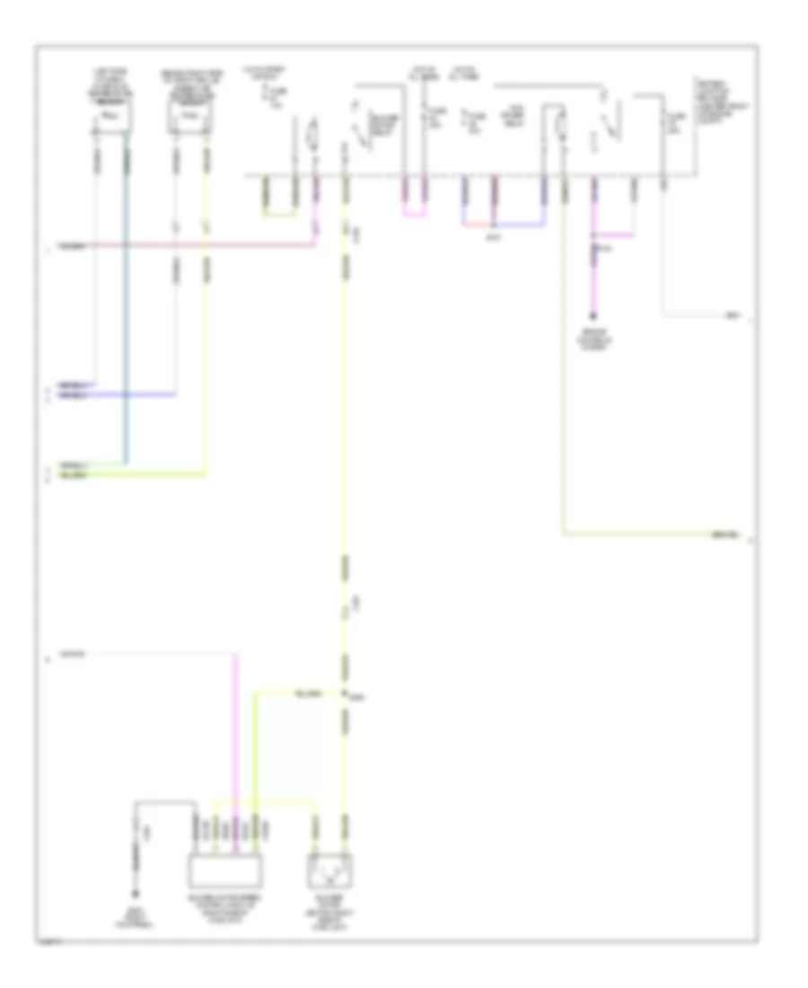
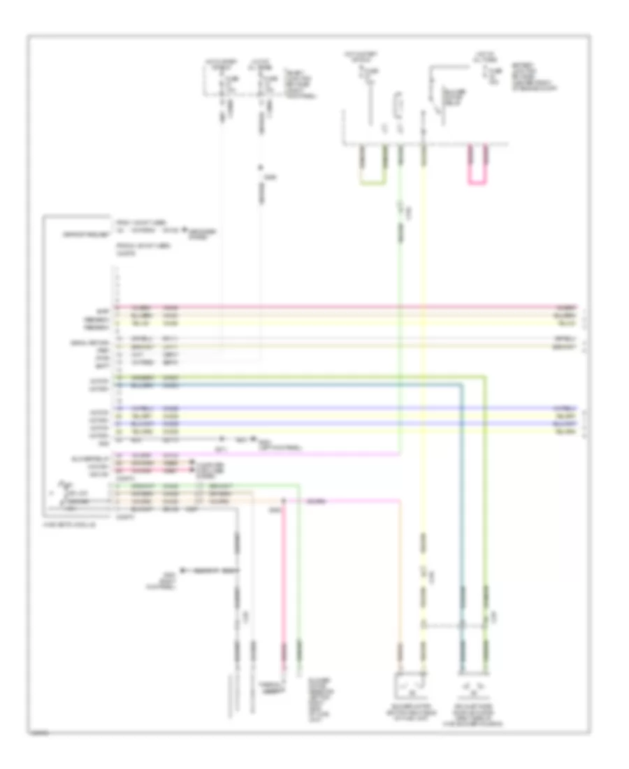
Automatic A/C Wiring Diagram, with Auxiliary Climate Control (2 of 4) for Ford Expedition EL XL 2014
List of elements for Automatic A/C Wiring Diagram, with Auxiliary Climate Control (2 of 4) for Ford Expedition EL XL 2014:
- (behind right side of front grille) ambient air temperature sensor
- (left side of dash) in-vehicle temperature sensor
- (taillights harness, near breakout to fuel tank) s437
- (top of hvac evaporator assembly) evaporator temperature sensor
- (under top center of dash) sunload sensor
- Auxiliary mode door actuator (front right side of auxiliary hvac unit)
- Auxiliary temperature blend door actuator (left side of auxiliary hvac unit)
- C210
- C214
- C2280a
- C2280b
- C2280d
- C299
- C411
- Fuse 10a
- Fuse 7.5a
- Headlights system
- Hot at all times
- Hot in start or run
- S204 (body main harness, in breakout to c211)
- S266
- S436 (taillights harness, near breakout to fuel tank)
- Smart junction box (sjb) (right kick panel)
- Solid state
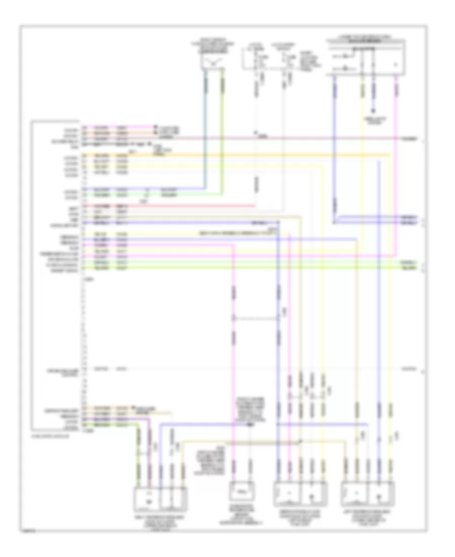
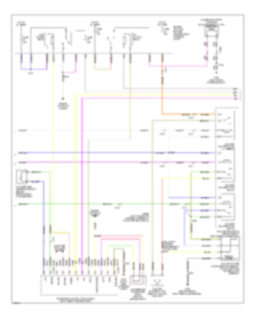
Automatic A/C Wiring Diagram, with Auxiliary Climate Control (3 of 4) for Ford Expedition EL XL 2014
List of elements for Automatic A/C Wiring Diagram, with Auxiliary Climate Control (3 of 4) for Ford Expedition EL XL 2014:
- (lower right front of engine) a/c compressor clutch field coil
- (navigator: engine control sensor harness, near breakout to front of engine compt) s126
- (rear light connector harness, in breakout to auxiliary relay box 2)
- (rear light connector harness, in breakout to auxiliary relay box 2) s420
- (right front of engine compt)
- (taillights harness, near breakout to fuel tank) s435
- A/c clutch relay
- A/c pressure transducer (right front of engine compt)
- Accr
- Acpt
- Auxiliary blower motor (rear of auxiliary hvac unit)
- Auxiliary blower motor relay 1
- Auxiliary blower motor relay 2
- Auxiliary blower motor relay 3
- Auxiliary blower motor resistor (on auxiliary hvac blower motor assembly)
- Auxiliary relay box 2 (behind rear of right rear quarterpanel)
- Battery junction box (bjb) (center front of engine compt)
- C1026
- C144
- C175b
- C175e
- C211
- C214
- C410
- C411
- Ce201
- Ce202
- Ce607
- Ch302
- Cht
- Computer data lines system
- Cylinder head temperature sensor (rear of right cylinder bank)
- Engine controls system
- Fuse 10a
- Fuse 20a
- Fuse 30a
- Fuse 40a
- G106
- G108 (right rear of engine compt)
- G403 (behind rear of right rear quarterpanel)
- Gd113
- Hfc
- Hot at all times
- Hs can+
- Hs can-
- Le424
- Lfc
- Pcm power relay
- Pcmrc
- Powertrain control module (pcm) (right rear of engine compt)
- Pwr gnd
- Re405
- Re407
- S103
- S122
- S127
- S422
- S428 (w/ power vent windows & third row folding seats)
- Signal return
- Sigrtn
- Thermal limiter
- Vdb04
- Vdb05
- Ve712
- Vh433
- Vref
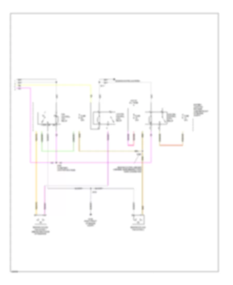
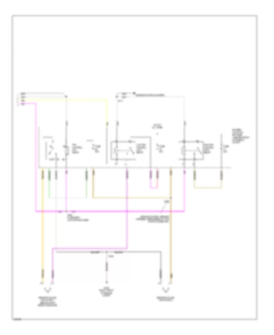
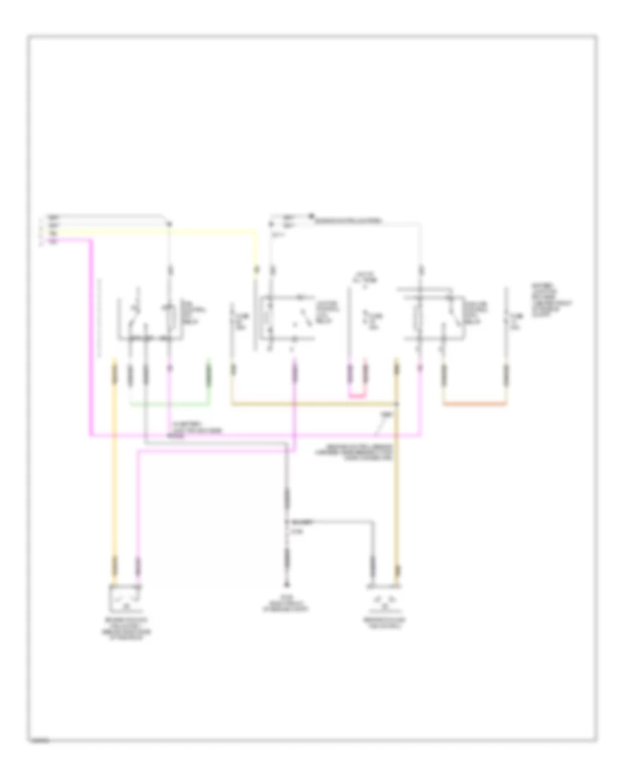
Automatic A/C Wiring Diagram, with Auxiliary Climate Control (4 of 4) for Ford Expedition EL XL 2014
List of elements for Automatic A/C Wiring Diagram, with Auxiliary Climate Control (4 of 4) for Ford Expedition EL XL 2014:
- (engine control sensor harness, near breakout for horn connector)
- 87a
- Battery junction box (bjb) (center front of engine compt)
- Engine controls system
- Engine cooling fan motor 1 (behind right side of radiator)
- Engine cooling fan motor 2
- Fan control (fc) relay
- Fuse 25a
- Fuse 40a
- G106 (right front of engine compt)
- High fan control (hfc) relay
- Hot at all times
- Low fan control (lfc) relay
- S108
- S111
- S162 (in battery junction box (bjb))
- S163
Automatic A/C Wiring Diagram, without Auxiliary Climate Control (1 of 4) for Ford Expedition EL XL 2014
List of elements for Automatic A/C Wiring Diagram, without Auxiliary Climate Control (1 of 4) for Ford Expedition EL XL 2014:
- (front heater blower motor harness, near breakout to right blend door actuator) s255
- (right side of hvac blower housing) air inlet mode door actuator
- (under top center of dash) sunload sensor
- Ambient signal
- Blower relay
- C2280a
- C2280b
- C228a
- C228b
- C291
- C299
- Cbp37
- Ch122
- Ch123
- Ch202
- Ch203
- Ch212
- Ch213
- Ch228
- Ch229
- Ch238
- Ch239
- Computer data lines system
- Defogger system
- Defrost request
- Defrost/panel/floor mode door actuator (left side of hvac unit)
- Driver sunload
- Evap
- Evaporator temperature sensor (top of hvac evaporator assembly)
- Feedback
- Fuse 10a
- G203 (left kick panel)
- Gd133
- Gnd
- Headlights system
- Hot at all times
- Hot in start or run
- Hvac (datc) module
- In-vehicle signal
- Left temperature blend door actuator (lower center of hvac unit)
- Lh111
- Motor+
- Motor-
- Ms can+
- Ms can-
- Passenger sunload
- Rh111
- Right temperature blend door actuator (upper center of hvac unit)
- S204 (body main harness, in breakout to c211)
- S211
- S254 (front heater blower motor harness, near breakout to right blend door actuator)
- S266
- Sbp15
- Signal return
- Smart junction box (sjb) (right kick panel)
- Solid state
- Variable blower control
- Vbatt
- Vdb06
- Vdb07
- Vh101
- Vh406
- Vh407
- Vh414
- Vh416
- Vh417
- Vh436
- Vh440
- Vh441
- Vpwr
- Vref
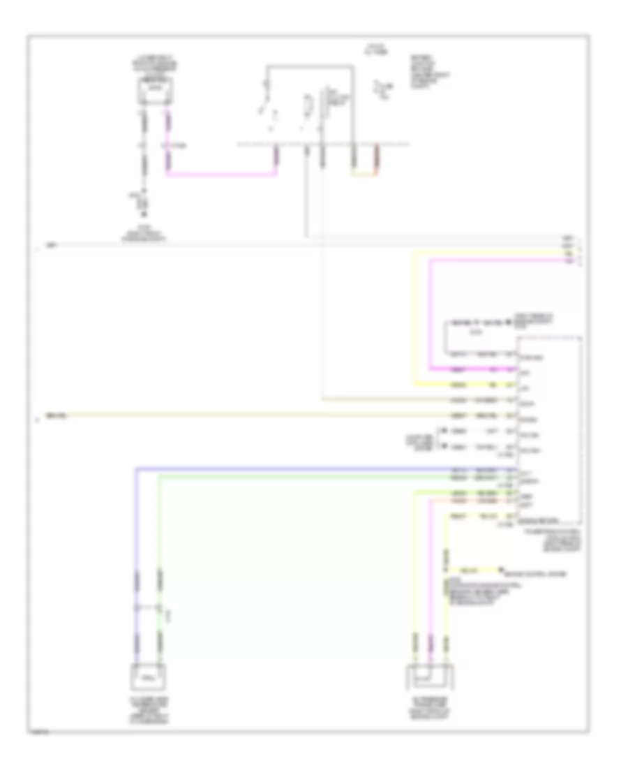
Automatic A/C Wiring Diagram, without Auxiliary Climate Control (2 of 4) for Ford Expedition EL XL 2014
List of elements for Automatic A/C Wiring Diagram, without Auxiliary Climate Control (2 of 4) for Ford Expedition EL XL 2014:
- (behind right side of front grille) ambient air temperature sensor
- (left side of dash) in-vehicle temperature sensor
- Battery junction box (bjb) (center front of engine compt)
- Blower motor (bottom right side of hvac unit)
- Blower motor relay
- Blower motor speed control module (right side of hvac unit)
- C210
- C291
- Ch402
- Engine controls system
- Fuse 10a
- Fuse 20a
- Fuse 40a
- G204 (right kick panel)
- Gd138
- Hot at all times
- Hot in start or run
- Pcm power relay
- S127
- S253
- Vh101
- Vh301
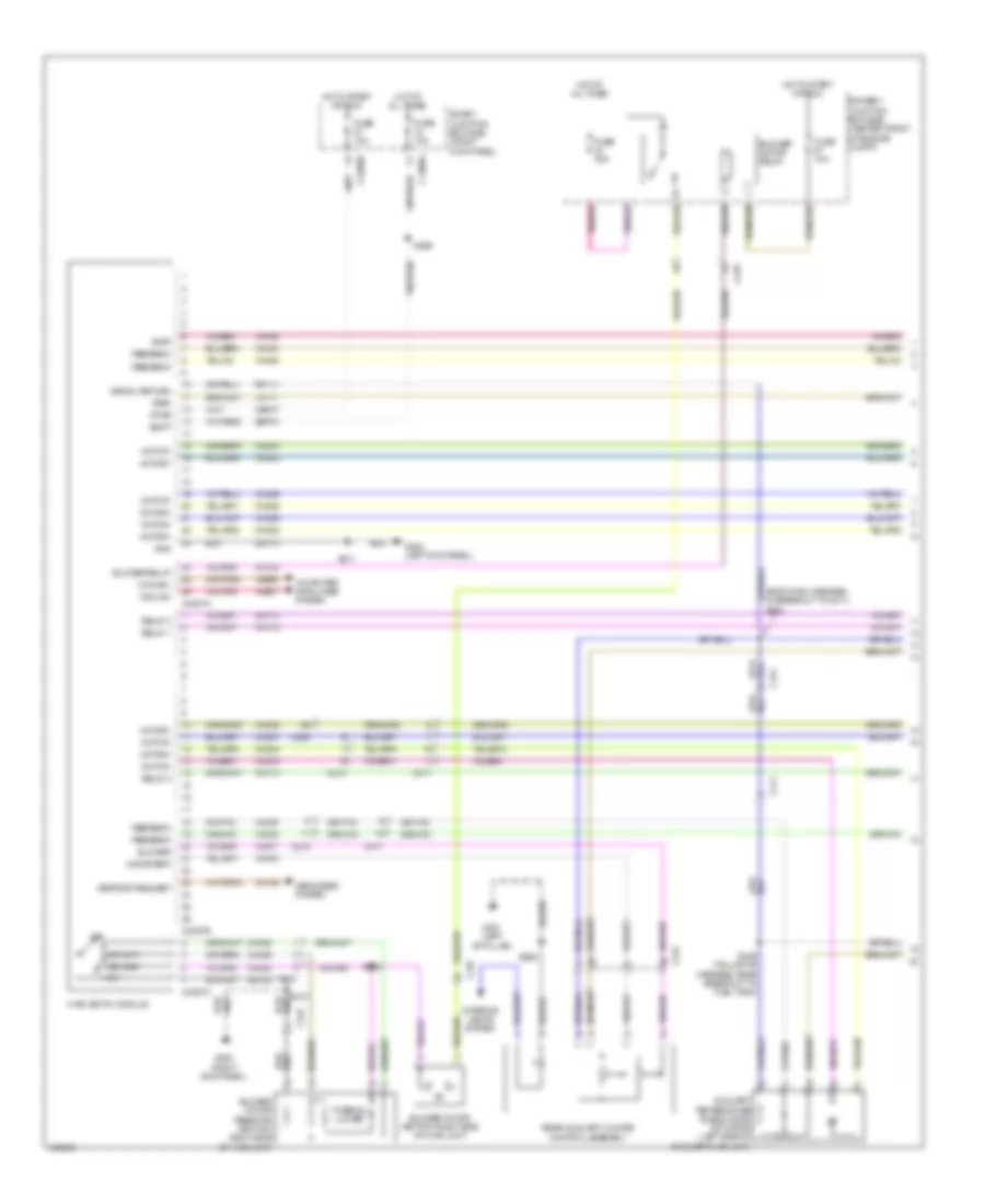
Automatic A/C Wiring Diagram, without Auxiliary Climate Control (3 of 4) for Ford Expedition EL XL 2014
List of elements for Automatic A/C Wiring Diagram, without Auxiliary Climate Control (3 of 4) for Ford Expedition EL XL 2014:
- (lower right front of engine) a/c compressor clutch field coil
- (right rear of engine compt) g108
- A/c clutch relay
- A/c pressure transducer (right front of engine compt)
- Accr
- Acpt
- Battery junction box (bjb) (center front of engine compt)
- C1026
- C144
- C175b
- C175e
- Ce201
- Ce202
- Ce607
- Ch302
- Cht
- Computer data lines system
- Cylinder head temperature sensor (rear of right cylinder bank)
- Engine control system
- Fuse 10a
- G106 (right front of engine compt)
- Gd113
- Hfc
- Hot at all times
- Hs can+
- Hs can-
- Le424
- Lfc
- Of engine compt)
- Pcmrc
- Powertrain control module (pcm) (right rear of engine compt)
- Pwr gnd
- Re405
- Re407
- S103
- S122
- Signal return
- Sigrtn
- Vdb04
- Vdb05
- Ve712
- Vh433
- Vref
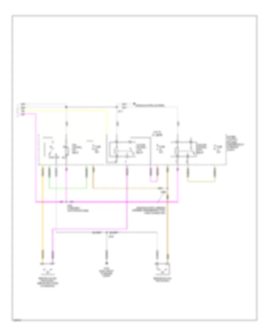
Automatic A/C Wiring Diagram, without Auxiliary Climate Control (4 of 4) for Ford Expedition EL XL 2014
List of elements for Automatic A/C Wiring Diagram, without Auxiliary Climate Control (4 of 4) for Ford Expedition EL XL 2014:
- (engine control sensor harness, near breakout for horn connector)
- 87a
- Battery junction box (bjb) (center front of engine compt)
- Engine controls system
- Engine cooling fan motor 1 (behind right side of radiator)
- Engine cooling fan motor 2
- Fan control (fc) relay
- Fuse 25a
- Fuse 40a
- G106 (right front of engine compt)
- High fan control (hfc) relay
- Hot at all times
- Low fan control (lfc) relay
- S108
- S111
- S162 (in battery junction box (bjb))
- S163
Manual A/C Wiring Diagram, with Auxiliary Climate Control (1 of 4) for Ford Expedition EL XL 2014
List of elements for Manual A/C Wiring Diagram, with Auxiliary Climate Control (1 of 4) for Ford Expedition EL XL 2014:
- (body main harness, in breakout to c211) s204
- Auxiliary temperature blend door actuator (left side of auxiliary hvac unit)
- Battery junction box (bjb) (center front of engine compt)
- Blower
- Blower motor (bottom right side of hvac unit)
- Blower motor relay
- Blower motor resistor (bottom right side of hvac unit)
- Blower relay
- C210
- C214
- C2280a
- C2280b
- C2357a
- C2357b
- C2357c
- C237
- C238
- C315
- C411
- Cbp37
- Ch112
- Ch113
- Ch114
- Ch122
- Ch123
- Ch202
- Ch203
- Ch207
- Ch208
- Ch228
- Ch229
- Ch233
- Ch234
- Ch238
- Ch239
- Ch428
- Ch429
- Ch430
- Computer data lines system
- Defogger system
- Defrost request
- Evap
- Feedback
- Fuse 10a
- Fuse 40a
- G200 (right kick panel)
- G203 (left kick panel)
- G301 (left "b" pillar)
- Gd113
- Gd138
- Gnd
- High
- Hot at all times
- Hot in start or run
- Hvac (emtc) module
- Interior lights system
- Lh111
- Mid high
- Mid low
- Mode/temp
- Motor+
- Motor-
- Ms can+
- Ms can-
- Off
- Rear auxiliary climate control assembly
- Relay 1
- Relay 2
- Relay 3
- Rh111
- S211
- S252
- S266
- S369
- S436 (taillights harness, near breakout to fuel tank)
- Sbp15
- Signal return
- Smart junction box (sjb) (right kick panel)
- Thermal limiter
- Vbatt
- Vdb06
- Vdb07
- Vh406
- Vh436
- Vh438
- Vh439
- Vh440
- Vha15
- Vha17
- Vpwr
- Vref
Manual A/C Wiring Diagram, with Auxiliary Climate Control (2 of 4) for Ford Expedition EL XL 2014
List of elements for Manual A/C Wiring Diagram, with Auxiliary Climate Control (2 of 4) for Ford Expedition EL XL 2014:
- (front heater blower motor harness, near breakout to right blend door actuator)
- Air inlet mode door actuator (right side of hvac blower housing)
- Auxiliary mode door actuator (front right side of auxiliary hvac unit)
- Below right side of dash)
- C214
- C2280d
- C237
- C299
- C411
- Defrost/panel/floor mode door actuator (left side of hvac unit)
- Evaporator temperature sensor (top of hvac evaporator assembly)
- Fuse 7.5a
- Hot in start or run
- S254 (front heater blower motor harness, near breakout to right blend door actuator)
- S255
- S437 (taillights harness, near breakout to fuel tank)
- Smart junction box (sjb) (right kick panel)
- Temperature blend door actuator (top right side of hvac unit)
Manual A/C Wiring Diagram, with Auxiliary Climate Control (3 of 4) for Ford Expedition EL XL 2014
List of elements for Manual A/C Wiring Diagram, with Auxiliary Climate Control (3 of 4) for Ford Expedition EL XL 2014:
- (lower right front of engine) a/c compressor clutch field coil
- (rear light connector harness, in breakout to auxiliary relay box 2)
- A/c clutch relay
- A/c pressure transducer (right front of engine compt)
- Accr
- Acpt
- Auxiliary blower motor (rear of auxiliary hvac unit)
- Auxiliary blower motor relay 1
- Auxiliary blower motor relay 2
- Auxiliary blower motor relay 3
- Auxiliary blower motor resistor assembly (on auxiliary hvac blower motor assembly)
- Auxiliary relay box 2 (behind rear of right rear quarterpanel)
- Battery junction box (bjb) (center front of engine compt)
- C1026
- C144
- C175b
- C175e
- C211
- C214
- C410
- C411
- Ce201
- Ce202
- Ce607
- Ch302
- Cht
- Computer data lines system
- Cylinder head temperature (cht) sensor (rear of right cylinder bank)
- Engine controls system
- Fuse 10a
- Fuse 20a
- Fuse 30a
- G106 (right front of engine compt)
- G108 (right rear of engine compt)
- G403 (behind rear of right rear quarterpanel)
- Gd113
- Hfc
- Hot at all times
- Hs can+
- Hs can-
- Le424
- Lfc
- Pcm power relay
- Pcmrc
- Powertrain control module (pcm) (right rear of engine compt)
- Pwr gnd
- Re405
- Re407
- S103
- S122
- S123
- S126
- S127
- S420
- S422
- S428
- Signal return
- Sigrtn
- Thermal limiter
- Vdb04
- Vdb05
- Ve712
- Vh433
- Vref
Manual A/C Wiring Diagram, with Auxiliary Climate Control (4 of 4) for Ford Expedition EL XL 2014
List of elements for Manual A/C Wiring Diagram, with Auxiliary Climate Control (4 of 4) for Ford Expedition EL XL 2014:
- (engine control sensor harness, near breakout for horn connector)
- 87a
- Battery junction box (bjb) (center front of engine compt)
- Engine controls system
- Engine cooling fan motor 1 (behind right side of radiator)
- Engine cooling fan motor 2
- Fan control (fc) relay
- Fuse 25a
- Fuse 40a
- G106 (right front of engine compt)
- High fan control (hfc) relay
- Hot at all times
- Low fan control (lfc) relay
- S108
- S111
- S162 (in battery junction box (bjb))
- S163
Manual A/C Wiring Diagram, without Auxiliary Climate Control (1 of 3) for Ford Expedition EL XL 2014
List of elements for Manual A/C Wiring Diagram, without Auxiliary Climate Control (1 of 3) for Ford Expedition EL XL 2014:
- (pins 1-22 not used)
- (pins 24 -26 not used)
- Air inlet mode door actuator (right side of hvac blower housing)
- Battery junction box (bjb) (center front of engine compt)
- Blower motor (bottom right side of hvac unit)
- Blower motor relay
- Blower motor resistor (bottom right side of hvac unit)
- Blower relay
- C210
- C2280a
- C2280b
- C2357a
- C2357b
- C2357c
- C237
- Cbp37
- Ch122
- Ch123
- Ch202
- Ch203
- Ch228
- Ch229
- Ch238
- Ch239
- Ch428
- Ch429
- Ch430
- Computer data lines system
- Defogger system
- Defrost request
- Evap
- Feedback
- Fuse 10a
- Fuse 40a
- G200 (right kick panel)
- G203 (left kick panel)
- Gd113
- Gd138
- Gnd
- High
- Hot at all times
- Hot in start or run
- Hvac (emtc) module
- Lh111
- Mid high
- Mid low
- Motor+
- Motor-
- Ms can+
- Ms can-
- Off
- Rh111
- S210
- S211
- S252
- S266
- Sbp15
- Signal return
- Smart junction box (sjb) (right kick panel)
- Thermal limiter
- Vbatt
- Vdb06
- Vdb07
- Vh406
- Vh436
- Vh440
- Vpwr
- Vref
Manual A/C Wiring Diagram, without Auxiliary Climate Control (2 of 3) for Ford Expedition EL XL 2014
List of elements for Manual A/C Wiring Diagram, without Auxiliary Climate Control (2 of 3) for Ford Expedition EL XL 2014:
- (front heater blower motor harness, near breakout to right blend door actuator) s254
- (front heater blower motor harness, near breakout to right blend door actuator) s255
- (lower right front of engine) a/c compressor clutch field coil
- A/c
- A/c pressure transducer (right front of engine compt)
- Accr
- Acpt
- Battery junction box (bjb) (center front of engine compt)
- C1026
- C144
- C175b
- C175e
- C237
- C299
- Ce201
- Ce202
- Ce607
- Ch302
- Cht
- Clutch
- Computer data lines system
- Cylinder head temperature (cht) sensor (rear of right cylinder bank)
- Defrost/panel/floor mode door actuator (left side of hvac unit)
- Engine controls system
- Evaporator temperature sensor (top of hvac evaporator assembly)
- Fuse 10a
- Fuse 20a
- Fuse 30a
- G106 (right front of engine compt)
- G108 (right rear of engine compt)
- Gd113
- Hfc
- Hot at all times
- Hs can+
- Hs can-
- Le424
- Lfc
- Pcm power relay
- Pcmrc
- Powertrain control module (pcm) (right rear of engine compt)
- Pwr gnd
- Re405
- Re407
- Relay
- S103
- S122
- S123
- S126
- S127
- Signal return
- Sigrtn
- Temperature blend door actuator (top right side of hvac unit)
- Vdb04
- Vdb05
- Ve712
- Vh433
- Vref
Manual A/C Wiring Diagram, without Auxiliary Climate Control (3 of 3) for Ford Expedition EL XL 2014
List of elements for Manual A/C Wiring Diagram, without Auxiliary Climate Control (3 of 3) for Ford Expedition EL XL 2014:
- (engine control sensor harness, near breakout for horn connector)
- (in battery junction box (bjb)) s162
- 87a
- Battery junction box (bjb) (center front of engine compt)
- Engine controls system
- Engine cooling fan motor 1 (behind right side of radiator)
- Engine cooling fan motor 2
- Fan control (fc) relay
- Fuse 25a
- Fuse 40a
- G106 (right front of engine compt)
- High fan control (hfc) relay
- Hot at all times
- Low fan control (lfc) relay
- S108
- S111
- S163