AIR CONDITIONING
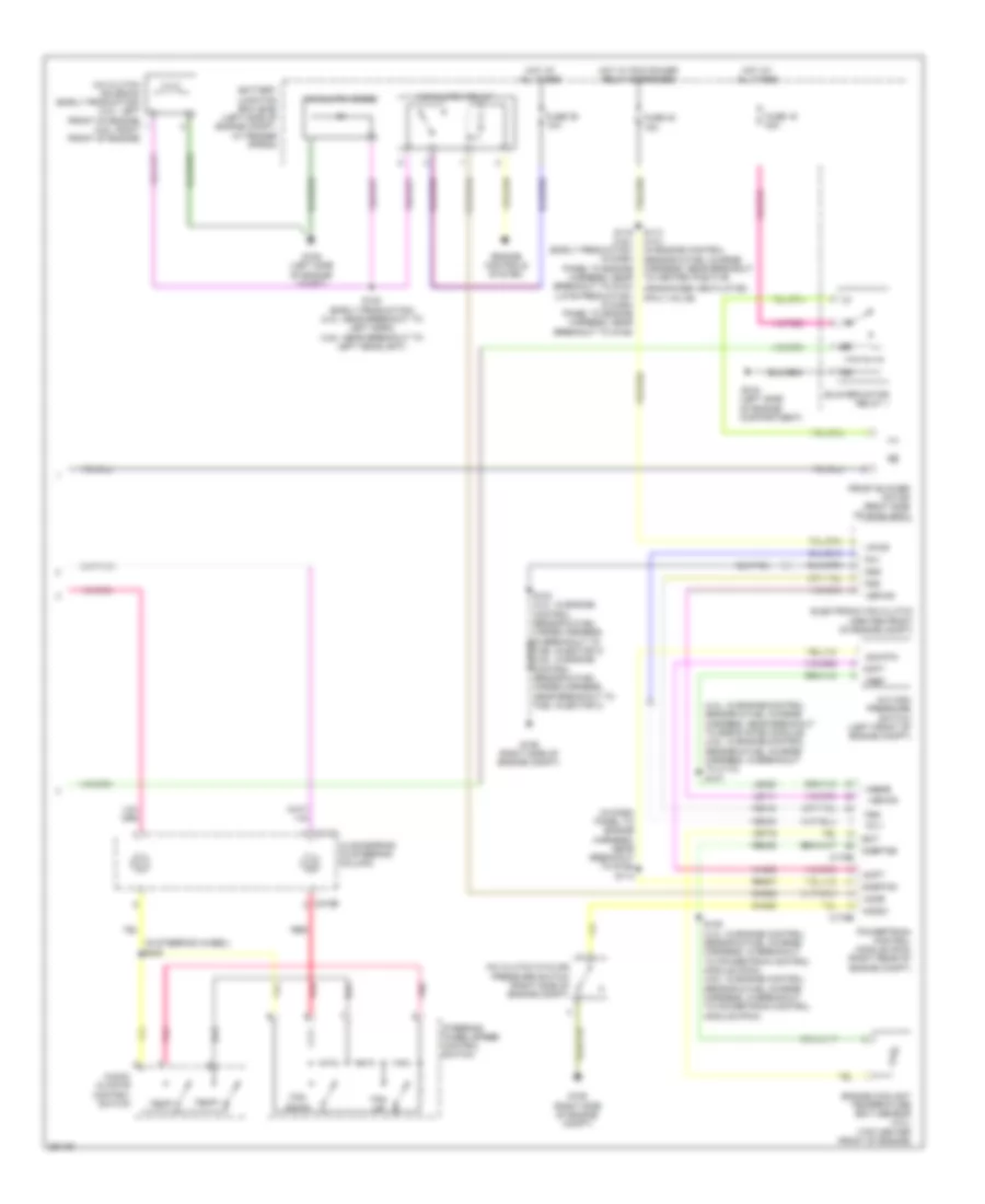
Automatic A/C Wiring Diagram (1 of 2) for Ford Explorer Sport Trac 2007

List of elements for Automatic A/C Wiring Diagram (1 of 2) for Ford Explorer Sport Trac 2007:
- (in air conditioner harness, near breakout for c211) s231
- (under right side of dash) g201
- Amb temp
- Ambient air temperature sensor (left front of engine compt, near radiator support)
- Anti- theft
- Autolamp/ sunload sensor (behind glove box)
- Bd pot
- Bd pot 5v
- Blower ctrl
- C2280c
- C2280d
- C228a
- C228b
- Cbp20
- Ch123
- Ch211
- Ch213
- Ch217
- Ch218
- Ch220
- Ch221
- Ch222
- Ch223
- Ch224
- Ch237
- Ch239
- Cln04
- Computer data lines system
- Dimming in
- Driver temperature blend door actuator (rear left side of hvac unit)
- Electronic automatic temperature control (eatc) module (behind lower center of dash)
- Fb out
- Front blower motor speed controller (center of hvac unit)
- Fuse 20 10a
- Fuse 24 10a
- Fuse 28 10a
- G302 (base of right "b" pillar)
- Gd145
- Gnd
- Ground
- Hat
- Hbr sw in
- Hot at all times
- Hot w/ run/start relay energized
- In car temp
- In-vehicle temperature sensor (behind left center of dash)
- Instrument cluster
- Interior lights system
- Left bd a+
- Left bd b-
- Left bd feedback
- Left sunload
- Lh111
- Ms can+
- Ms can-
- Mtr sink
- Passenger temperature blend door actuator (front left side of hvac unit)
- Pwr gnd
- Remote solenoid assembly (behind center of dash)
- Rh104
- Rh106
- Rh111
- Rh226
- Right bd a+
- Right bd b-
- Right bd feedback
- Right sunload
- Run/start
- S202 (in main harness, near breakout to passenger air bag module)
- S219 (in main harness, near breakout to deployable steering column)
- Sbp28
- Sense a/d
- Smart junction box (sjb) (behind left side of dash)
- Sn gnd
- Steering sw in
- Steering sw rtn
- Vac 1
- Vac 2
- Vac 3
- Vac 4
- Vac 5
- Vac 5 hcwv
- Vac gnd
- Var spd in
- Vbc fb
- Vbc hbr
- Vbc out
- Vdb06
- Vdb07
- Vh219
- Vh407
- Vh414
- Vh416
- Vh417
- Vh440
- Vh441
- Vh444
Automatic A/C Wiring Diagram (2 of 2) for Ford Explorer Sport Trac 2007
List of elements for Automatic A/C Wiring Diagram (2 of 2) for Ford Explorer Sport Trac 2007:
- (4.0l: in engine control sensor & fuel charge harness, near breakout to egr system module) (4.6l: in engine control sensor & fuel charge harness, in breakout to c110) s107
- (in dash panel to engine harness, near breakout to g106) s114
- (in steering wheel) s240
- A/c clutch cycling pressure switch (right side of engine compt)
- A/c clutch diode
- A/c clutch relay
- A/c clutch solenoid (early production) (4.0l: left front of engine) (4.6l: right front of engine)
- A/c high pressure switch (left front of engine compt)
- Accr
- Acds1
- Acpt
- Audio/ climate control switch
- Battery junction box (bjb) (left side of engine compt, at fender apron)
- Blower motor relay 1
- C175b
- C175e
- C218a
- C218b
- Ch302
- Ch423
- Clockspring (in steering column)
- Crankcase ventilation (pcv) valve)
- Ect
- Electronic fan clutch (center front of engine compt)
- Engine controls system
- Engine coolant temperature (ect) sensor (4.0l) (top center front of engine)
- Fan down
- Fan up
- Fc-v
- Fcv
- Front blower motor (right side of hvac unit)
- Fss
- Fuel injector 3) (4.6l: in engine control sensor & fuel harge harness, near breakout to fuel injector 3)
- Fuse 16 40a
- Fuse 35 10a
- Fuse 40 15a
- G105 (left side of engine compartment)
- G105 (left side of engine compt)
- G106 (right side of engine compt)
- Gnd
- Hot at all times
- Hot w/ pcm power relay energized
- Le111
- Le423
- Pnk
- Powertrain control module (pcm) (right rear of engine compt)
- Re405
- Re407
- Red
- S105 (4.0l: in engine control sensor & fuel charge harness, in breakout to powertrain control module (pcm)) (4.6l: in engine control sensor & fuel charge harness, in breakout to powertrain control module (pcm))
- S113 (4.0l) (in engine control sensor & fuel charge harness, near breakout to heated positive
- S119 (4.6l) (early production: in dash panel to engine harness, near breakout to g104) (late production: in dash panel to engine harness, near breakout to g105)
- S123 (early production) (4.0l: near breakout to left horn) (4.6l: near breakout to left headlight)
- Sig rtn
- Sigrtnc
- Sigrtne
- Steering wheel/speed control switch
- Temp+
- Temp-
- Vbpwr
- Ve716
- Vec03
- Vec10
- Vh433
- Vpwr
- Vref
- Vrefe
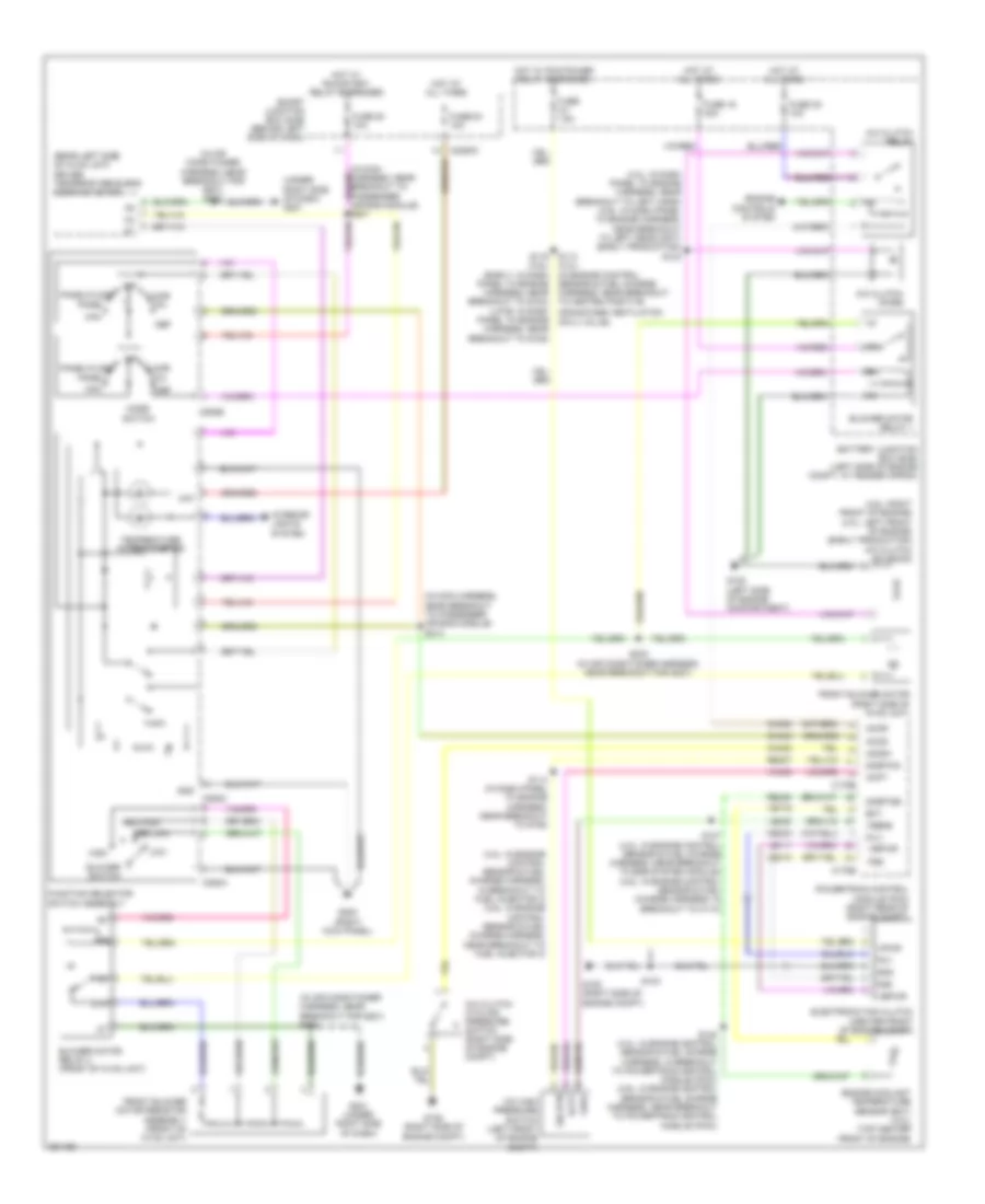
Manual A/C Wiring Diagram for Ford Explorer Sport Trac 2007
List of elements for Manual A/C Wiring Diagram for Ford Explorer Sport Trac 2007:
- (4.0l: in dash panel to engine harness, near breakout to left horn) (4.6l: in dash panel to engine harness, near breakout to left headlight) (early production) s123
- (4.0l: in engine control sensor & fuel charge harness, in breakout to fuel injector 3) (4.6l: in engine control sensor & fuel charge harness, near breakout to fuel injector 3)
- (4.6l: right front of engine) (4.0l: left front of engine) (early production) a/c clutch solenoid
- (in air conditioner harness, near breakout for g201)
- (in air conditioner harness, near breakout for g201) s232
- (in main harness, near breakout to passenger air bag module) s213
- (rear left side of hvac unit) driver temperature blend door actuator
- (under right side of dash) g201
- 87a
- A/c clutch cycling pressure switch (right side of engine compt)
- A/c clutch diode
- A/c clutch relay
- A/c high pressure switch (left front of engine compt)
- Accr
- Accs
- Acds1
- Acpt
- Battery junction box (bjb) (left side of engine compt, at fender apron)
- Blower motor relay 1
- Blower motor relay 2 (front of hvac unit)
- Blower switch
- C175b
- C175e
- C2280c
- C294a
- C294b
- C294c
- Ch302
- Ch423
- Ch443
- Crankcase ventilation (pcv) valve)
- Def
- Ect
- Electronic fan clutch (center front of engine compt)
- Engine controls system
- Engine coolant temperature sensor (ect) (4.0l) (top center front of engine)
- Fc-v
- Fcv
- Floor
- Front blower motor (right side of hvac unit)
- Front blower motor resistor assembly (front of hvac unit)
- Fss
- Function selector switch assembly
- Fuse 15a
- Fuse 16 40a
- Fuse 20 10a
- Fuse 28 10a
- Fuse 35 10a
- G105 (left side of engine compartment)
- G106 (right side of engine compt)
- G200 (right kick panel)
- G201 (under right side of dash)
- Gnd
- Hat
- High
- Hot at all times
- Hot w/ pcm power relay energized
- Hot w/ run/start relay energized
- Interior lights system
- Le111
- Le423
- Low
- Max
- Med high
- Med low
- Mix
- Mode switch
- Off
- Panel
- Panel/floor
- Powertrain control module (pcm) (right rear of engine compt)
- Re405
- Re407
- S103
- S105 (4.0l: in engine control sensor & fuel charge harness, in breakout to powertrain control module (pcm)) (4.6l: in engine control sensor & fuel charge harness, near breakout to powertrain control module (pcm))
- S107 (4.0l: in engine control sensor & fuel charge harness, near breakout to egr system module) (4.6l: in engine control sensor & fuel charge harness, in breakout to c110)
- S113 (4.0l) (in engine control sensor & fuel charge harness, near breakout to heated positive
- S114 (in dash panel to engine harness, near breakout to g106)
- S119 (4.6l) (early: in dash panel to engine harness, near breakout to g104) (late: in dash panel to engine harness, near breakout to g105)
- S233
- Sig rtn
- Sigrtnc
- Sigrtne
- Smart junction box (sjb) (behind left side of dash)
- Temperature potentiometer
- Vbpwr
- Ve716
- Vec03
- Vec10
- Vh433
- Vpwr
- Vref
- Vrefe