AIR CONDITIONING
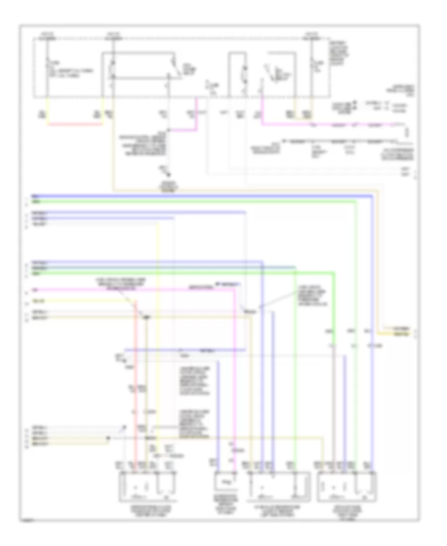
Automatic A/C Wiring Diagram (1 of 3) for Ford F-150 STX 2014

List of elements for Automatic A/C Wiring Diagram (1 of 3) for Ford F-150 STX 2014:
- (left side of dash) g203
- (or ch212)
- (or ch213)
- (or vh441)
- (right side of dash) blower motor
- (w/ ambient lighting)
- Act fdbk
- Air inlet dr fdbk
- Autolamp sensor in
- Autolamp/sunload sensor (center of dash)
- Battery junction box (bjb) (front of engine compt)
- Blower control
- Blower motor relay
- Blower motor speed control (right side of dash)
- Body control module (right kick panel)
- C213
- C214
- C2280a
- C2280b
- C2280f
- C228a
- C228b
- C260
- C263
- Ch122
- Ch123
- Ch207
- Ch208
- Ch228
- Ch229
- Ch238
- Ch239
- Chs02
- Chs07
- Computer data lines system
- Crd02
- Defogger system
- Defrost request
- Defrost status
- Door ccw
- Door cw
- Driver sunload
- Drv heated st pwr
- Drv heater feed
- Drv st ntc sens
- Eatc hvac module
- Evap temp sen
- Front blower rly
- Fuse 10a
- Fuse 30a
- Fuse 40a
- Fuse 5a
- G202 (left side of dash)
- Gd133
- Gnd
- Hot at all times
- Hot in run or start
- Hs can+
- Hs can-
- Humidity sens
- Left side temperature blend door actuator (center of dash)
- Lh111
- Mode 1 act fdbk
- Mode door 1ccw
- Mode door 1cw
- Motor +
- Motor -
- Ms can+
- Ms can-
- Pass heated st pwr
- Pass heater feed
- Pass st ntc sens
- Pass sunload
- Pwm
- Recirc ccw
- Recirc cw
- Return
- Rh111
- Right side temperature blend door actuator (right side of dash)
- S156
- S222
- S229 (main wiring harness, near breakout to passenger air bag module)
- S260
- S449
- Sbb69
- Sbp46
- Seats system
- Temp sens
- Vbatt
- Vdb04
- Vdb05
- Vdb06
- Vdb07
- Vh101
- Vh406
- Vh413
- Vh414
- Vh416
- Vh417
- Vh436
- Vh438
- Vh440
- Vhs26
- Vhs27
- Vlf14
- Vref
- W/ dual zone
- W/o dual zone
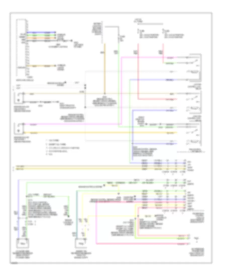
Automatic A/C Wiring Diagram (2 of 3) for Ford F-150 STX 2014
List of elements for Automatic A/C Wiring Diagram (2 of 3) for Ford F-150 STX 2014:
- (3.5l turbo)
- (6.2l)
- (except 3.5l turbo)
- (except 6.2l)
- (heater blower motor wiring harness, in breakout to defrost/panel/ floor mode door actuator)
- (heater blower motor wiring harness, near breakout to defrost/panel/ floor mode door actuator)
- (main wiring harness, near breakout to passenger air bag module)
- A/c clutch relay
- A/c compressor clutch field coil (a/c compressor)
- Air inlet mode door actuator (right side of dash)
- Battery junction box (bjb) (front of engine compt)
- C1010
- C192
- C263
- Computer data lines system
- Defrost/panel/floor mode door actuator (center of dash)
- Engine controls system
- Evaporator temperature sensor (right side of dash)
- Fuse 10a
- Fuse 40a 50a
- G101 (right front of engine compt)
- Hot at all times
- Hs can+
- Hs can-
- In-vehicle temperature/ humidity sensor (left side of dash)
- Instrument panel cluster (ipc)
- Pcm power relay
- S125 (engine control sensor wiring harness, near breakout to mass air flow/intake air temperature sensor)
- S208
- S209
- S228
- S247
- Seats system
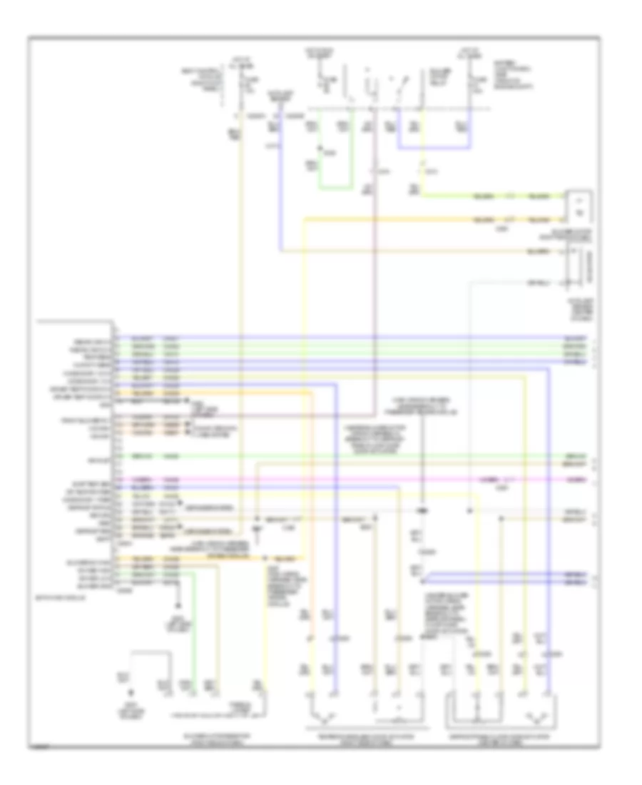
Automatic A/C Wiring Diagram (3 of 3) for Ford F-150 STX 2014
List of elements for Automatic A/C Wiring Diagram (3 of 3) for Ford F-150 STX 2014:
- (3.5l turbo) s113
- (engine control sensor wiring harness, near breakout to engine cooling fan motor 1)
- (or re454)
- (right front of engine compt) g101
- (w/ svt raptor)
- (w/o svt raptor)
- 3.5l turbo
- 3.7l lpg, 3.7l cng & 3.7l flex fuel
- 5.0l flex fuel & 6.2l
- 50a
- 6.2l
- A/c pressure transducer (right front of engine compt)
- Aat
- Accr
- Acpt
- Ambient air temperature sensor (front of engine compt)
- Battery junction box (bjb) (front of of engine compt)
- C1026
- C133
- C1381b
- C1381e
- C1551b
- C1551e
- C175b
- C175e
- C228c
- Ce607
- Cec01
- Cec02
- Ch302
- Cht
- Computer data lines system
- Cylinder head temperature sensor (rear of right cylinder head)
- Eatc hvac module
- Engine controls system
- Engine cooling fan motor 1 (behind radiator)
- Engine cooling fan motor 2 (behind radiator)
- Except 3.5l turbo
- Fan control (fc) relay
- Fuse 25a
- Fuse 40a
- G101 (right front of of engine compt)
- G202 (left side of dash)
- Gd133
- Gnd
- Green
- Hfc
- High fan control (hfc) relay
- Hot at all times
- Hs can +
- Hs can -
- Interior lights system
- Le424
- Lfc
- Low fan control (lfc) relay
- Pcmrc
- Powertrain control module (right rear of engine compt)
- Re405
- Re407
- Red
- Return
- Rln44
- S105
- S141 (3.5l turbo) s162 (except 3.5l turbo) (except 3.5l turbo: engine control sensor wiring harness, near breakout to c144)
- S154
- S169 (engine control sensor wiring harness, near breakout to g101)
- S169 (except 3.5l turbo) (engine control sensor wiring harness, near breakout to g101)
- S173 (6.2l & 5.0l flex fuel) (5.0l flex fuel: engine control sensor & fuel charge wiring harness, near breakout to c1019) (6.2l: engine control sensor & fuel charge wiring harness, near breakout to c133)
- S183 (engine control sensor wiring harness, near breakout to engine cooling fan motor 1)
- S197 (engine control sensor wiring harness, near breakout to engine cooling fan motor 1)
- S260 (w/ ambient lighting)
- Sigrtn
- Vdb04
- Vdb05
- Ve712
- Ve750
- Vh433
- Vln44
- Vln45
- Vln46
- Vref
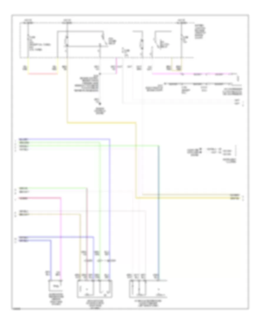
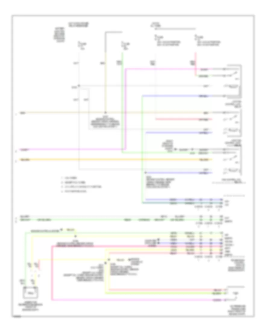
Manual A/C Wiring Diagram, Base (1 of 3) for Ford F-150 STX 2014
List of elements for Manual A/C Wiring Diagram, Base (1 of 3) for Ford F-150 STX 2014:
- (heater blower motor wiring harness, in breakout to defrost/ panel/floor mode door actuator)
- (heater blower motor wiring harness, near breakout to defrost/panel/ floor mode door actuator) s209
- (main wiring harness, near breakout to passenger air bag module)
- Air inlet
- Autolamp sensor (center of dash)
- Autolamp sensor in
- Battery junction box (bjb) (front of engine compt)
- Blower gnd
- Blower motor (right side of dash)
- Blower motor relay
- Blower motor resistor (right side of dash)
- Blower sw high
- Body control module (right kick panel)
- C213
- C214
- C2280a
- C2280b
- C260
- C263
- C294a
- C294b
- Ch122
- Ch123
- Ch207
- Ch208
- Ch228
- Ch229
- Ch238
- Ch239
- Ch426
- Ch428
- Ch429
- Computer data lines system
- Crd02
- Defogger system
- Defrost req
- Defrost status
- Defrost/panel/floor mode actuator (center of dash)
- Dr temp dr fdbk
- Driver temp door ccw
- Driver temp door cw
- Emtc hvac module
- Evap temp sen
- Front blower rly
- Fuse 10a
- Fuse 40a
- Fuse 5a
- G202 (left side of dash)
- G203 (left side of dash)
- Gd133
- Gd138
- Gnd
- Hot at all times
- Hot in run or start
- Humidity sens
- Lh111
- Mode door 1 ccw
- Mode door 1 cw
- Mode door 1 fdbk
- Ms can+
- Ms can-
- Recirc dr ccw
- Recirc dr cw
- Return
- Rh111
- S156
- S208
- S227 (main wiring harness, near breakout to passenger air bag module)
- S228
- S247
- Sbp46
- Solid state
- Sw med high
- Sw med low
- Temp sens
- Temperature blend door actuator (right side of dash)
- Thermal limiter
- Vbatt
- Vdb06
- Vdb07
- Vh406
- Vh413
- Vh414
- Vh436
- Vh438
- Vh440
- Vlf14
- Vref
Manual A/C Wiring Diagram, Base (2 of 3) for Ford F-150 STX 2014
List of elements for Manual A/C Wiring Diagram, Base (2 of 3) for Ford F-150 STX 2014:
- (6.2l)
- (except 6.2l)
- A/c clutch relay
- A/c compressor clutch field coil (a/c compressor)
- Air inlet mode door actuator (right side of dash)
- Battery junction box (bjb) (front of engine compt)
- C1010
- C192
- C263
- Computer data lines system
- Engine controls system
- Evaporator temperature sensor (right side of dash)
- Fuse 10a
- Fuse 40a (except 3.5l turbo) 50a (3.5l turbo)
- G101 (right front of engine compt)
- Hot at all times
- Hs can+
- Hs can-
- In-vehicle temperature/ humidity sensor (left side of dash)
- Instrument cluster
- Pcm power relay
- S125 (engine control sensor wiring harness, near breakout to mass air flow/intake air temperature sensor)
Manual A/C Wiring Diagram, Base (3 of 3) for Ford F-150 STX 2014
List of elements for Manual A/C Wiring Diagram, Base (3 of 3) for Ford F-150 STX 2014:
- (0r re454)
- (engine control sensor wiring harness, near breakout to engine cooling fan motor 1)
- (engine control sensor wiring harness, near breakout to g101)
- (right front of of engine compt) g101
- (w/ svt raptor)
- (w/o svt raptor)
- 3.5l turbo
- 3.7l lpg, 3.7l cng & 3.7l flex fuel
- 5.0l flex fuel & 6.2l
- 50a
- 6.2l
- A/c pressure transducer (right front of engine compt)
- Aat
- Accr
- Acpt
- Ambient air temperature sensor (front of engine compt)
- Battery junction box (bjb) (front of of engine compt)
- C1026
- C133
- C1381b
- C1381e
- C1551b
- C1551e
- C175b
- C175e
- Ce607
- Cec01
- Cec02
- Ch302
- Cht
- Computer data lines system
- Cylinder head temperature sensor (rear of right cylinder head)
- Engine controls system
- Engine cooling fan motor 1 (behind radiator)
- Engine cooling fan motor 2 (behind radiator)
- Except 3.5l turbo
- Fan control (fc) relay
- Fuse 25a
- Fuse 40a
- G101 (right front of of engine compt)
- Hfc
- High fan control (hfc) relay
- Hot at all times
- Hs can +
- Hs can -
- Le424
- Lfc
- Low fan control (lfc) relay
- Near breakout to c133)
- Pcmrc
- Powertrain control module (right rear of engine compt)
- Re405
- Re407
- S105
- S154
- S162 (except 3.5l turbo) s141 (3.5l turbo) (except 3.5l turbo: engine control sensor wiring harness, near breakout to c144)
- S169
- S169 (except 3.5l) (engine control sensor wiring harness, near breakout to g101)
- S183 (engine control sensor wiring harness, near breakout to engine cooling fan motor 1)
- S197 (engine control sensor wiring harness, near breakout to engine cooling fan motor 1)
- Sig rtn
- Vdb04
- Vdb05
- Ve712
- Ve750
- Vh433
- Vref
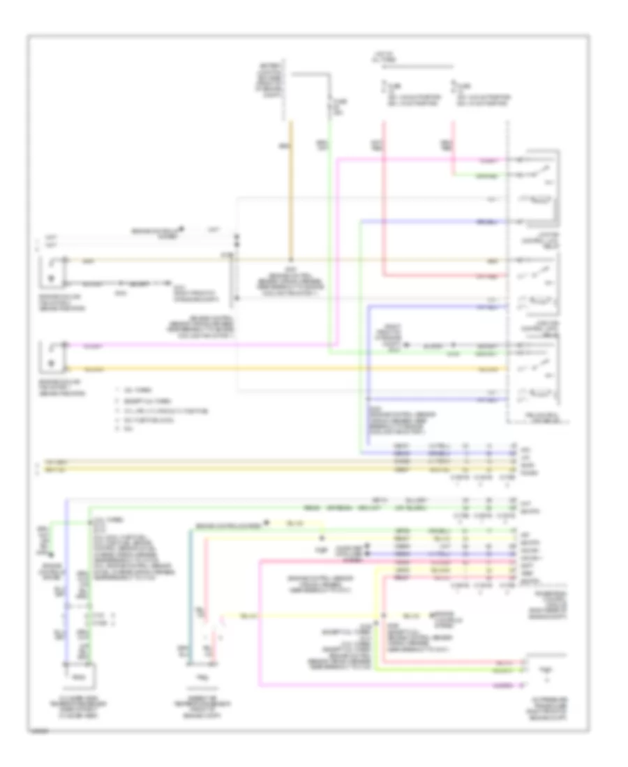
Manual A/C Wiring Diagram, Except Base (1 of 3) for Ford F-150 STX 2014
List of elements for Manual A/C Wiring Diagram, Except Base (1 of 3) for Ford F-150 STX 2014:
- (heater blower motor wiring harness, in breakout to defrost/ panel/floor mode door actuator)
- (heater blower motor wiring harness, near breakout to defrost/ panel/floor mode door actuator)
- (main wiring harness, near breakout to passenger air bag module)
- 40a
- Act fdbk
- Air inlet dr fdbk
- Battery junction box (bjb) (front of engine compt)
- Blower control
- Blower motor relay
- Body control module (right kick panel)
- C213
- C214
- C2280a
- C2357a
- C2357b
- C263
- Ch122
- Ch123
- Ch207
- Ch208
- Ch228
- Ch229
- Ch238
- Ch239
- Computer data lines system
- Crd02
- Defogger system
- Defrost request
- Defrost status
- Defrost/panel/floor mode actuator (center of dash)
- Door ccw
- Door cw
- Emtc hvac module
- Evap temp sen
- Ft blower relay
- Fuse
- Fuse 10a
- G202 (left side of dash)
- Gd133
- Gnd
- Hot at all times
- Hot in start or run
- Humidity sens
- Left side temperature blend door actuator (center of dash)
- Lh111
- Mode 1 act fdbk
- Mode door 1ccw
- Mode door 1cw
- Ms can+
- Ms can-
- Recirc ccw
- Recirc cw
- Return
- Rh111
- S156
- S208
- S209
- S247
- Sbp46
- Temp sens
- Vbatt
- Vdb06
- Vdb07
- Vh101
- Vh406
- Vh413
- Vh414
- Vh436
- Vh438
- Vh440
- Vref
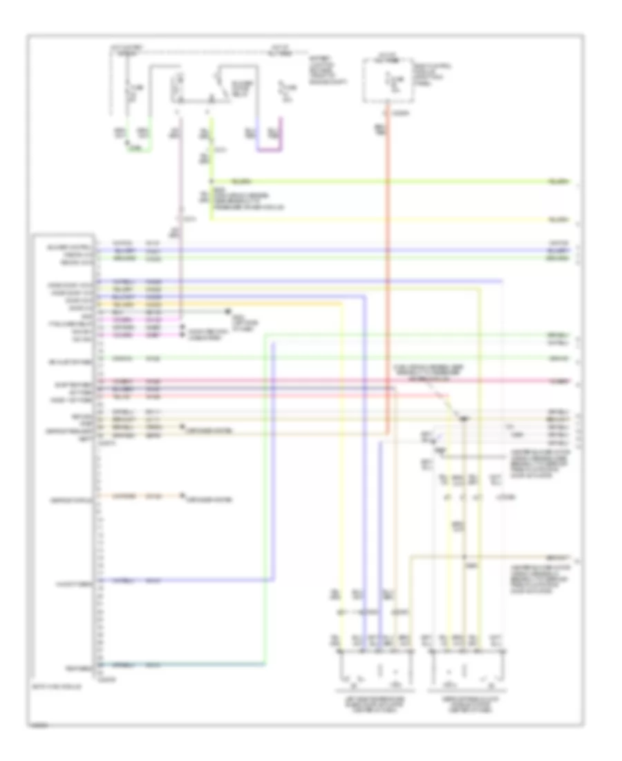
Manual A/C Wiring Diagram, Except Base (2 of 3) for Ford F-150 STX 2014
List of elements for Manual A/C Wiring Diagram, Except Base (2 of 3) for Ford F-150 STX 2014:
- (3.5l turbo) s113
- (3.7l lpg, 3.7l cng & 3.7l flex fuel)
- (6.2l)
- (behind radiator) engine cooling fan motor 1
- (behind radiator) engine cooling fan motor 2
- (main wiring harness, near breakout to passenger air bag module)
- (right side of dash) blower motor
- (right side of dash) blower motor speed control
- Air inlet mode door actuator (right side of dash)
- C1026
- C133
- C260
- C263
- Cylinder head temperature sensor (rear of right cylinder head)
- Engine controls system
- Evaporator temperature sensor (right side of dash)
- G101 (right front of engine compt)
- G203 (left side of dash)
- Gnd
- In-vehicle temperature/ humidity sensor (left side of dash)
- Motor +
- Motor -
- Pwm
- S154
- S173 (6.2l & 5.0l fuel flex) (5.0l fuel flex: engine control sensor & fuel charge wiring harness, near breakout to c1019) (6.2l: engine control sensor & fuel charge wiring harness, near breakout to c133)
- S228
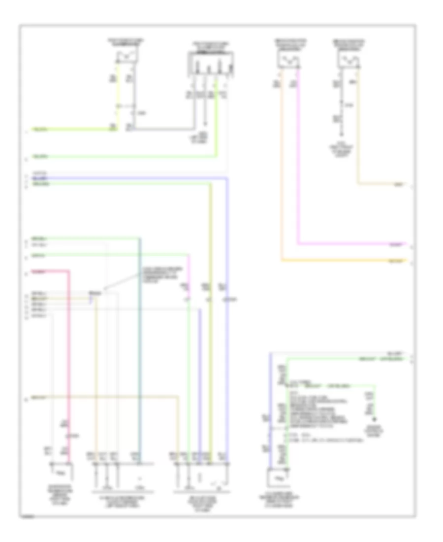
Manual A/C Wiring Diagram, Except Base (3 of 3) for Ford F-150 STX 2014
List of elements for Manual A/C Wiring Diagram, Except Base (3 of 3) for Ford F-150 STX 2014:
- (or re454)
- (right front of of engine compt) g101
- (w/ svt raptor)
- (w/o svt raptor)
- 3.5l turbo
- 3.7l lpg, 3.7l cng & 3.7l flex fuel
- 5.0l flex fuel & 6.2l
- 50a
- A/c pressure transducer (right front of engine compt)
- Aat
- Acpt
- Ambient air temperature sensor (front of engine compt)
- Battery junction box (bjb) (front of of engine compt)
- C1381b
- C1381e
- C1551b
- C1551e
- C175b
- C175e
- Cec01
- Cec02
- Cht
- Computer data lines system
- Engine controls system
- Except 3.5l turbo
- Fan control (fc) relay
- Fuse 10a
- Fuse 25a
- Fuse 40a
- Hfc
- High fan control (hfc) relay
- Hot at all times
- Hot w/ pcm power relay energized
- Hs can +
- Hs can -
- Le424
- Lfc
- Low fan control (lfc) relay
- Powertrain control module (right rear of engine compt)
- Re405
- Re407
- S105
- S141 (3.5l turbo) s162 (except 3.5l turbo) (except 3.5l turbo: engine control sensor wiring harness, near breakout to c144)
- S154
- S169 (engine control sensor wiring harness, near breakout to g101)
- S169 (except 3.5l turbo) (engine control sensor wiring harness, near breakout to g101)
- S183 (engine control sensor wiring harness, near breakout to engine cooling fan motor 1)
- S197 (engine control sensor wiring harness, near breakout to engine cooling fan motor 1)
- Sigrtn
- Vdb04
- Vdb05
- Ve712
- Ve750
- Vh433
- Vref