AIR CONDITIONING
Heater Wiring Diagram for Ford F450 Super Duty 2001

List of elements for Heater Wiring Diagram for Ford F450 Super Duty 2001:
- (center of dash) g206
- (in engine harness, near breakout to ground, right side of engine compartment, near battery) s180
- (in main harness, near break out to customer access) s290
- (in main harness, near breakout to brake pedal position (bpp) switch) s235 (2000) s235 (2001) (in main harness, near breakout to data link connector (dlc))
- (right side of engine compartment, near battery) g111
- 0.3 ohms
- 0.7 ohms
- 1.7 ohms
- 87a
- Battery junction box (in left side of engine compartment, on top of wheelwell)
- Blend door actuator (behind right side of dash)
- Blend door potentiometer
- Blower motor (on right side of firewall)
- Blower motor relay
- Blower motor resistor (on right side of firewall, on plenum)
- Blower motor switch
- C225
- C242a
- C242b
- C260
- C296
- C298
- Central junction box (behind lower left side of dash)
- Climate control illumination
- Cold
- Defrost
- Floor
- Floor/defrost
- Function selector switch
- Fuse 22 10a
- Fuse 23 40a
- Fuse 24 10a
- High
- Hot at all times
- Hot in run
- Interior lights system
- Low
- Med high
- Med low
- Mode selector switch
- Off
- Panel
- Panel/floor
- Solid state
- To air bag diagnostic module) s257
- Warm
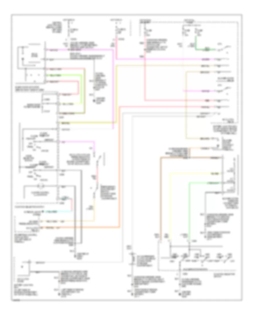
6.8L
6.8L, Manual A/C Wiring Diagram for Ford F450 Super Duty 2001
List of elements for 6.8L, Manual A/C Wiring Diagram for Ford F450 Super Duty 2001:
- (center of dash) g206
- (in engine harness, near breakout to 8 pin in-line connector, left side of engine compartment, near brake pressure switch) s102
- (in engine harness, near breakout to ground, right side of engine compartment, near battery) s180
- (in engine harness, near breakout to red
- (in engine sensor harness, near breakout to blower motor resistor) s152
- (in main harness, near break out to customer access) s290
- (in main harness, near breakout to customer access) s290
- (left rear of engine compartment, on firewall) g116
- (right side of engine compartment, near battery) g111
- 0.3 ohms
- 0.7 ohms
- 1.7 ohms
- 40 pin in-line connector, left of steering column) s123
- 87a
- A/c
- A/c clutch cycling pressure switch (in right rear of engine compartment, on a/c accumulator)
- A/c clutch diode
- A/c clutch relay
- A/c compressor clutch solenoid (in right side of engine compartment)
- A/c head pressure switch
- Battery junction box (in left side of engine compartment, on top of wheelwell)
- Blend door actuator (behind right side of dash)
- Blend door potentiometer
- Blower motor (on right side of firewall)
- Blower motor relay
- Blower motor resistor (on right side of firewall, on plenum)
- Blower motor switch
- Breakout to brake pedal position (bpp) switch) s235 (2000)
- C225
- C242a
- C242b
- C260
- C296
- C298
- Central junction box (behind lower left side of dash)
- Climate control illumination
- Cold
- Defrost
- Floor
- Floor/ defrost
- Function selector switch
- Fuse 10a
- Fuse 20a
- Fuse 22 10a
- Fuse 24 10a
- Fuse 40a
- High
- Hot at all times
- Hot in run
- Hot in run or start
- Interior lights system
- Low
- Max a/c
- Med high
- Med low
- Mode selector switch
- Off
- Pan/flr
- Panel
- Powertrain control module (pcm) (on left side of firewall)
- Red
- Refrigerant containment switch (in right side of engine compartment)
- S235 (2001) (in main harness, near breakout to data link connector (dlc))
- Solid state
- To air bag diagnostic module) s257
- Warm
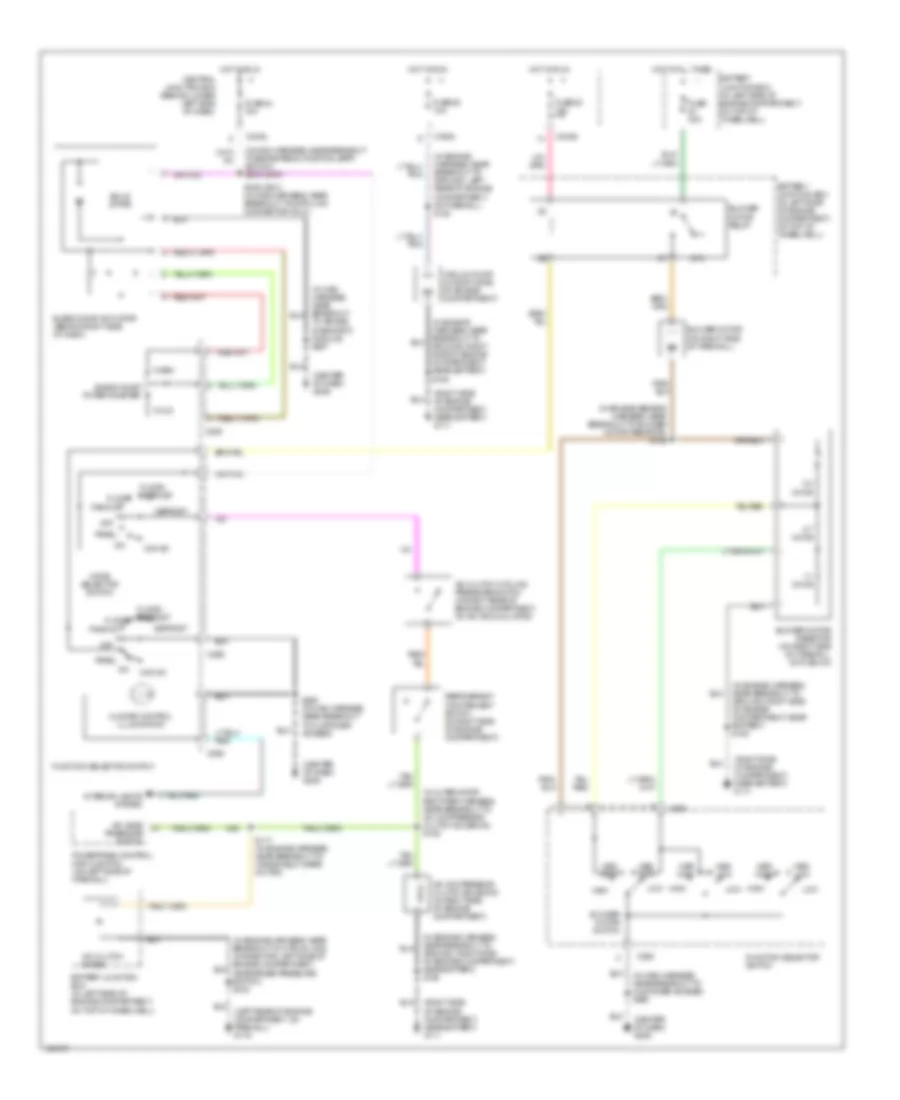
7.3L DI TURBO DIESEL
7.3L DI Turbo Diesel, Manual A/C Wiring Diagram for Ford F450 Super Duty 2001
List of elements for 7.3L DI Turbo Diesel, Manual A/C Wiring Diagram for Ford F450 Super Duty 2001:
- (center of dash) g206
- (in alternator rectifier harness, near breakout to a/c compressor clutch solenoid) s125
- (in engine harness, near breakout to ground, left rear of engine compartment, on firewall) s124
- (in engine harness, near breakout to ground, right side of engine compartment, near battery) s180
- (in engine sensor harness, near breakout to blower motor resistor) s152
- (in main harness, near breakout to brake pedal position (bpp) switch) s235 (2000)
- (in main harness, near breakout to customer access) s290
- (right side of engine compartment, near battery) g111
- 0.3 ohms
- 0.7 ohms
- 1.7 ohms
- 87a
- A/c
- A/c clutch cycling pressure switch (in right rear of engine compartment, on a/c accumulator)
- A/c clutch diode
- A/c compressor clutch solenoid (in right side of engine compartment)
- A/c head pressure switch
- Battery junction box (in left side of engine compartment, on top of wheelwell)
- Blend door actuator (behind right side of dash)
- Blend door potentiometer
- Blower motor (on right side of firewall)
- Blower motor relay
- Blower motor resistor (on right side of firewall, on plenum)
- Blower motor switch
- C225
- C242a
- C242b
- C260
- C296
- C298
- Central junction box (behind lower left side of dash)
- Climate control illumination
- Cold
- Defrost
- Floor
- Floor/ defrost
- Function selector switch
- Fuse 22 10a
- Fuse 24 10a
- Fuse 28 10a
- Fuse 40a
- High
- Hot at all times
- Hot in run
- Interior lights system
- Low
- Max a/c
- Med high
- Med low
- Mode selector switch
- Off
- Pan/flr
- Panel
- Powertrain control module (pcm) (on left side of firewall)
- Refrigerant containment switch (in right side of engine compartment)
- S117 (in engine harness, near breakout to windshield wiper motor)
- S235 (2001) (in main harness, near breakout to data link connector (dlc))
- S290 (in main harness, near breakout to customer access)
- Solid state
- To air bag diagnostic module) s257
- Vacuum pump (in right side of engine compartment)
- Warm