AIR CONDITIONING
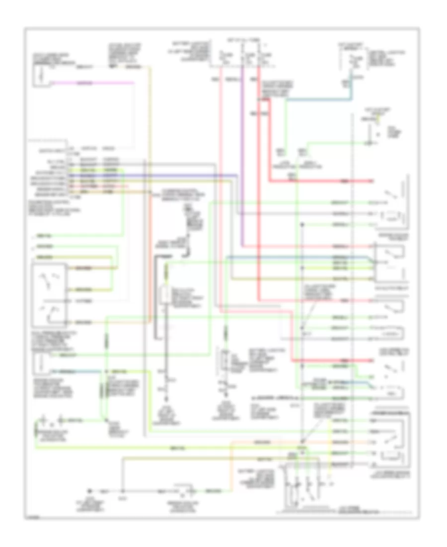
Manual A/C Wiring Diagram (1 of 2) for Ford Focus ZX3 SES 2006

List of elements for Manual A/C Wiring Diagram (1 of 2) for Ford Focus ZX3 SES 2006:
- (at left ``a" pillar) g204
- (at right ``a" pillar) g203
- 15-fa13
- 15s-fa38
- 29-fa13
- 29s-le10
- 31s-fa26
- 31s-hb22
- 31s-hb31
- 32-fa76
- 33-fa76
- 91-fa13
- 91s-fa20
- A/c compressor cycling switch (1: pressure increasing) (2: pressure decreasing) (in right rear corner of engine compartment)
- A/c on
- A/c switch
- A/c switch illumination
- Battery junction box (bjb) (in left rear corner of engine compartment)
- Blower motor resistor (behind center of dash)
- C270a
- C270e
- Central junction box (cjb) (behind left side of dash)
- Defogger system
- Deicing switch
- Fuse 40a
- Fuse 7.5a
- G203 (at right ``a" pillar)
- Heater blower motor (behind center of dash)
- Heater blower switch
- Heater control module (behind dash)
- High
- Hot at all times
- Hot in start or run
- Interior lights system
- Low speed
- Med high
- Med low
- Off
- Rear window heater on
- Rear window heater switch
- Rear window heater switch illumination
- Recirculation air actuator (behind right side of dash, next to blower motor)
- Recirculation on
- Recirculation switch
- Recirculation switch illumination
- S206
- S212
- S224 (in main wiring harness, near breakout for hazard flasher switch)
- Solid state
Manual A/C Wiring Diagram (2 of 2) for Ford Focus ZX3 SES 2006
List of elements for Manual A/C Wiring Diagram (2 of 2) for Ford Focus ZX3 SES 2006:
- (in engine control wiring harness, near breakout for c144)
- (in fuel shut-off solenoid wiring harness, near breakout to coil on plug 3) s198
- (in junction box wiring harness,
- (in junction box wiring harn, near battery junction box)
- (in junction box wiring harness, near breakout for c134)
- (left side of engine nca compt)
- (not used)
- (on cylinder head) cylinder head temperature sensor
- 15s-re8
- 31s-fa11
- 31s-pa17
- 31s-pa21
- 31s-pa7
- 8-pa13
- 8-rj33
- 87a
- 9-re8
- A/c clutch field coil (at right front of engine compartment)
- A/c clutch relay
- A/c com- pressor clutch diode
- Battery junction box (bjb) (in left rear corner of engine compartment)
- C1045
- C175b
- C175e
- C270c
- Central junction box (bjb) (behind left side of dash)
- Dual pressure switch 1) normal pressure 2) high pressure (at right front of engine compartment)
- Early production
- Engine cooling fan motor (on radiator)
- Engine cooling fan relay
- Engine cooling fan resistor (in front of engine compartment, near engine cooling fan)
- Fuse 10a
- Fuse 20a
- Fuse 50a
- G100 (at left front of engine compartment)
- G100 (at left front of engine compartment)
- G102 (at right front of engine compartment)
- G103 (at left side of engine compartment)
- Ground
- Ground switched
- High speed fan control relay
- Hot at all times
- Hot in start or run
- Late production
- Low speed cooling fan relay b
- Low speed engine cooling fan relay a
- Nca
- Near battery junction box) s107
- Pcm power diode
- Power distribution system
- Power hold relay
- Powertrain control module (pcm) (behind right side of dash, at base of ``a" pillar)
- Red
- Rly ctrl
- S1002 (near breakout to c134)
- S117
- S118
- S121
- S134
- S163
- S189 (right rear of engine, in harn)
- Second cooling fan motor (on radiator)
- Sensor return
- Sensor signal
- Switch input
- Switched volt