AIR CONDITIONING
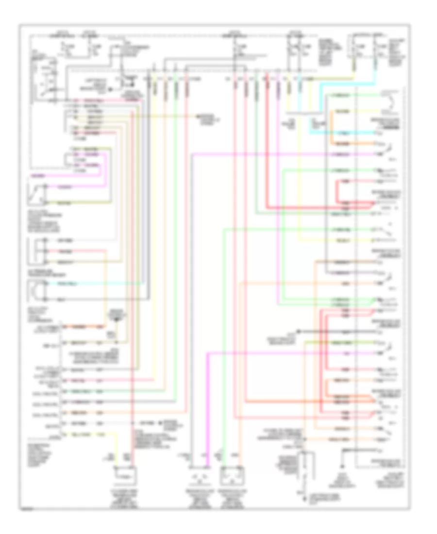
Automatic A/C Wiring Diagram (1 of 2) for Ford Freestar SE 2006

List of elements for Automatic A/C Wiring Diagram (1 of 2) for Ford Freestar SE 2006:
- (in heater blower motor harness, near breakout to c212) s234
- (in main harness, near breakout to joint connector 1) s202
- (right kick panel) g201
- A/c clutch req
- Ambient air temperature sensor (at right front side of engine compt)
- Ambient temp rtn(-)
- Ambient temp sns(+)
- Autolamp/ sunload sensor (near top center of dash)
- Blend dr close
- Blend dr feed
- Blend dr open
- Blower req
- Breakout for c214)
- Bussed electrical center (bec) (at left side of engine compt)
- C1035d a5
- C2280a
- C2280b
- C2280c
- C2280h
- C228a
- C228b
- Climate illum
- Computer data lines system
- Defrost feed
- Driver temperature blend door actuator (behind left side of dash)
- Electronic automatic temperature control (eatc) module (behind center of dash)
- Fresh/recirculation door actuator (behind center of dash)
- Front blower motor (behind right side of dash)
- Front blower motor relay (left kick panel)
- Front blower motor speed controller (behind right side of dash)
- Front blower out
- Frt hvac blwr
- Fuse 10a
- Fuse 30a
- Fuse 5a
- G301 (left kick panel)
- Ground
- Headlights system
- Heat/cool seat
- Hi htd seat
- Hot at all times
- Hot in run
- Htd seat req
- In-vehicle temperature sensor (behind left side of dash)
- Instrument cluster system
- L sunload sens
- Lo htd seat
- Low current board
- Mode actuator
- Mode door actuator (behind center of dash)
- P/fl/def close
- P/fl/def open
- Passenger temperature blend door actuator (behind right side of dash)
- Pnk
- R sunload sens
- Rear def req
- Rear defog ind
- Rear defog sw
- Recirc dr close
- Recirc dr open
- Rr def status
- S201 (in main harness, in breakout to c214)
- S203 (in main harn, near breakout to passenger airbag module)
- S228 (in main harness, near breakout to joint connector 1)
- S229 (in main harness, near breakout to front blower motor resistor assembly)
- S235 (in heater blower motor harness, near breakout to c212)
- Scp sig a (-)
- Scp sig b (+)
- Seat lo status
- Seats systems
- Shift interlock system
- Sjb-illum
- Smart junction box (sjb) (behind left side of dash)
- Sound systems
- Temp sens
- Temp sens gnd
- V-ign
- Vbatt
- Vbc output
- Vref actuator
- Vref mode rtn
- Vref rtn (gnd)
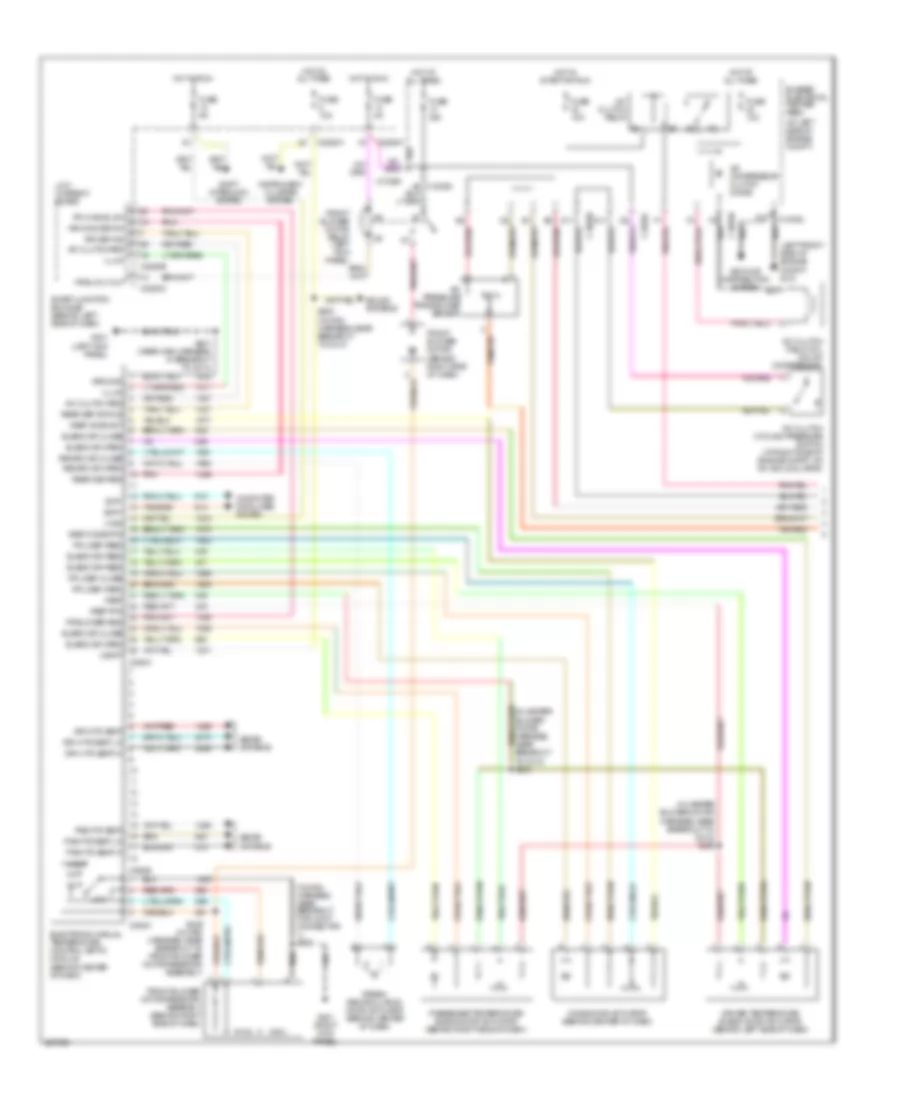
Automatic A/C Wiring Diagram (2 of 2) for Ford Freestar SE 2006
List of elements for Automatic A/C Wiring Diagram (2 of 2) for Ford Freestar SE 2006:
- (in dash to headlight junction harness, near breakout to c1024) s113
- (left front side of engine compt) g101
- 87a
- A/c cl cycl & hi press cutout input
- A/c clutch cycling pressure switch (at right side of engine compt, on a/c accumulator)
- A/c clutch field coil (on a/c compressor)
- A/c clutch relay
- A/c compressor clutch diode
- A/c cutout relay
- A/c hi press cutout input
- A/c pressure transducer sensor
- A10
- A11
- Auxiliary relay box 1 (right front of engine compt)
- Bussed electrical center (bec) (at left side of engine compt)
- C1035a
- C1035b
- C1035c
- C1035c f7
- C11 c1035b
- Chts
- Cool fan ctrl
- Cylinder head temperature sensor (rear of left cylinder head)
- D11
- Dropping resistor (left front of engine compt)
- E11
- Engine controls system
- Engine cooling fan circuit breaker
- Engine cooling fan motor 1 (behind left side of radiator)
- Engine cooling fan motor 2 (behind right side of radiator)
- Engine cooling fan relay 1
- Engine cooling fan relay 2
- Engine cooling fan relay 3
- Engine cooling fan relay 4
- Engine cooling fan relay 5
- F11
- Fuse 10a
- Fuse 15a
- Fuse 30a
- Fuse 40a
- G107 (right front of engine compt)
- Ground distribution system
- Hot at all times
- Hot in start or run
- Powertrain control module (pcm) (right rear of engine compt)
- Red
- Ref volt
- S102 (in engine control sensor & fuel charge harness, near breakout for g104)
- S106 (in engine control sensor & fuel charge harness, near breakout for g104)
- Sig rtn
- Tan/red
- W/ trailer tow
- W/o trailer tow
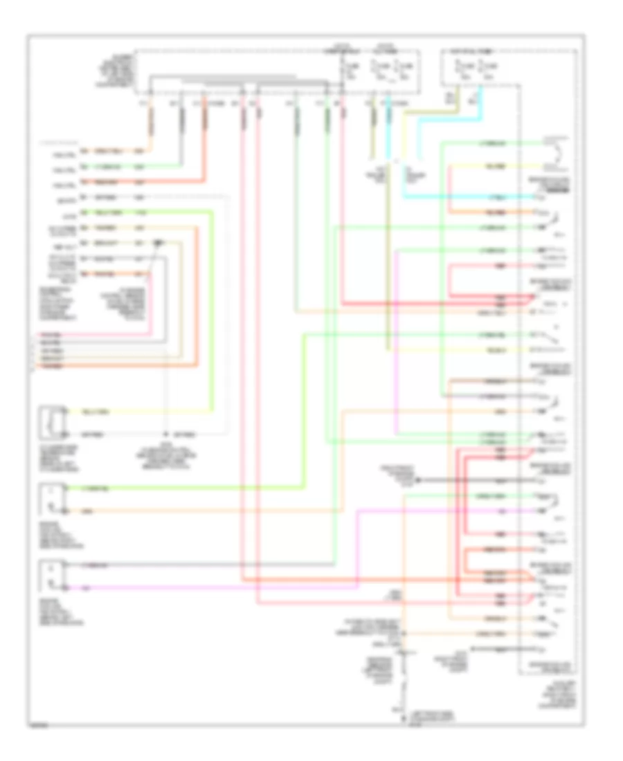
Manual A/C Wiring Diagram (1 of 2) for Ford Freestar SE 2006
List of elements for Manual A/C Wiring Diagram (1 of 2) for Ford Freestar SE 2006:
- (at left side of engine compt)
- (behind center of dash)
- (in heater blower motor harness, near breakout to c212) s235
- (in main harness, near breakout for joint connector 1) s202
- (left front side of engine compt) g101
- A/c clutch cycling pressure switch (at right side of engine compt, on a/c accumulator)
- A/c clutch field coil (on a/c compressor)
- A/c clutch relay
- A/c clutch req
- A/c compressor clutch diode
- A/c pressure transducer sensor
- A10
- Blend dr close
- Blend dr feed
- Blend dr open
- Bussed electrical center (bec)
- C1035a
- C1035b
- C1035c
- C2280a
- C2280b
- C2280c
- C2280h
- C294a
- C294b
- C294c
- Computer data lines system
- D11
- Driver temperature blend door actuator (behind left side of dash)
- Drv htd seat
- Drv htd seat hi
- Drv htd seat lo
- Electronic manual temperature control (emtc) module
- Fr bl rly out
- Fr blower req
- Fr hvac bl sw
- Fresh/ recirculation door actuator (behind center of dash)
- Front blower motor (behind right side of dash)
- Front blower motor relay (left kick panel)
- Front blower motor resistor assembly (behind right side of dash)
- Fuse 10a
- Fuse 15a
- Fuse 30a
- Fuse 5a
- G201 (right kick panel)
- G301 (left kick panel)
- Ground
- Ground distribution system
- High
- Hot at all times
- Hot in run
- Hot in start or run
- Illum
- Instrument cluster system
- Low
- Low current board
- Mode door actuator (behind center of dash)
- P/fl/def close
- P/fl/def feed
- P/fl/def open
- Pas htd seat
- Pas htd seat hi
- Pas htd seat lo
- Passenger temperature blend door actuator (behind right side of dash)
- Pnk
- Rear def req
- Rear def status
- Recirc dr close
- Recirc dr open
- Rr def ind
- Rr wdo def sw
- S200 (in main harness, near breakout to c214)
- S201 (near main harness, in breakout to c214)
- S229 (in main harness, near breakout to front blower motor resistor assembly)
- Scp+
- Scp-
- Seats systems
- Shift interlock system
- Smart junction box (sjb) (behind left side of dash)
- Sound systems
- Tan/red
- V-batt
- V-ign
- Vref
- Vref mode act
- Vref mode rtn
- Vref rtn
Manual A/C Wiring Diagram (2 of 2) for Ford Freestar SE 2006
List of elements for Manual A/C Wiring Diagram (2 of 2) for Ford Freestar SE 2006:
- (in dash to headlight junction harness, near breakout to c1024) s113
- (in engine control sensor & fuel charge harness, near breakout to g104)
- (left front side of engine compt) g101
- (right front of engine compt) g107
- 87a
- A/c cl cyc & hi press cutout in
- A/c cutout relay
- A/c hi pres cutout in
- A11
- Auxiliary relay box 1 (right front of engine compartment)
- Bussed electrical center (bec) (at left side of engine compartment)
- C1035b c11
- Chts
- Cylinder head temperature sensor (rear of left cylinder head)
- Dropping resistor (left front of engine compt)
- E11
- Engine cooling fan circuit breaker
- Engine cooling fan motor 1 (behind left side of radiator)
- Engine cooling fan motor 2 (behind right side of radiator)
- Engine cooling fan relay 1
- Engine cooling fan relay 2
- Engine cooling fan relay 3
- Engine cooling fan relay 4
- Engine cooling fan relay 5
- F11
- F7 c1035c
- Fan ctrl
- Fuse 15a
- Fuse 30a
- Fuse 40a
- G107 (right front of engine compt)
- Hot at all times
- Hot in start or run
- Powertrain control module (pcm) (right rear of engine compartment)
- Red
- Ref volt
- S102
- S106 (in engine control sensor & fuel charge harness, near breakout to g104)
- Sig rtn
- Tan/red
- W/ trailer tow
- W/o trailer tow
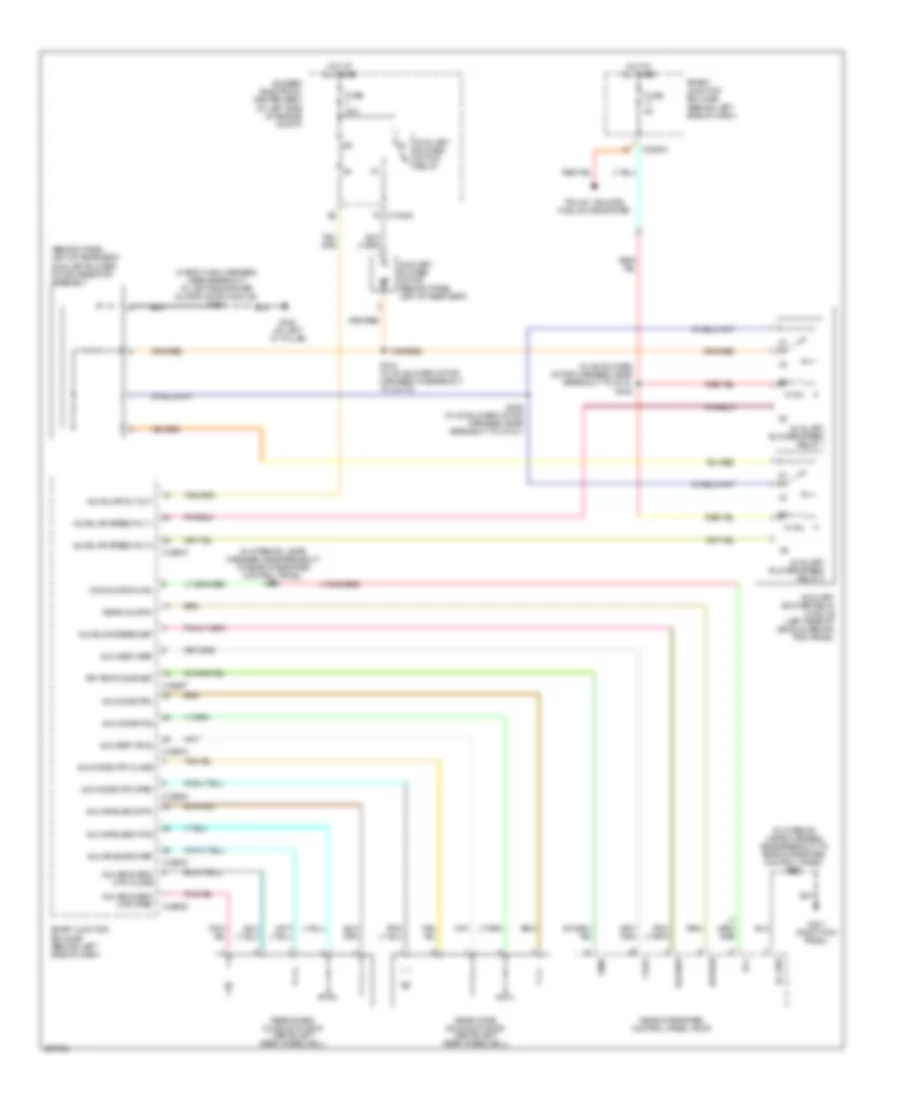
Rear A/C Wiring Diagram for Ford Freestar SE 2006
List of elements for Rear A/C Wiring Diagram for Ford Freestar SE 2006:
- (behind panel, left of rear seat) auxiliary blower motor resistor assembly
- (in a/c blower motor harness, near breakout to c315) s345
- (in interior lamps harness, near breakout to rear integrated control panel) s901
- (in interior lamps harness, near breakout to rear integrated control panel) s902
- (n body main harness, near breakout to left side power sliding door module) s310
- Aux air blend mtr close
- Aux air blend mtr open
- Aux air blend pos
- Aux air blend ref
- Aux air blend rtn
- Aux blwr rly out
- Aux blwr speed rly 1
- Aux blwr speed rly 2
- Aux blwr speed set
- Aux head vref
- Aux mode mtr close
- Aux mode mtr open
- Aux mode pos
- Aux mode trn
- Aux vref (pos)
- Auxiliary blower motor (behind panel, left of rear seat)
- Auxiliary blower motor relay
- Auxiliary blower relay module (left rear of vehicle, behind trim panel)
- Auxiliary blower speed relay 1
- Auxiliary blower speed relay 2
- Blower
- Bussed electrical center (bec) (at left side of engine compt)
- C2280c
- C2280d
- C2280f
- C2280h
- Dvd/ohc/rr hvac
- F4 c1035a
- Fuse 30a
- Fuse 5a
- G201 (right kick panel)
- G400 (at left ``d" pillar)
- Hot at all times
- Ill gnd
- Ill+
- Rear aux rtn
- Rear blend door actuator (above left rear wheelwell)
- Rear integrated control panel (ricp)
- Rear mode door actuator (above left rear wheelwell)
- Return
- Rr temp mode set
- S344 (in a/c blower motor harness, in breakout to c3172)
- S346 (in a/c blower motor harness, near breakout to c3121)
- Smart junction box (sjb) (behind left side of dash)
- Temp
- Trunk, tailgate, fuel doors system
- V-ref