AIR CONDITIONING
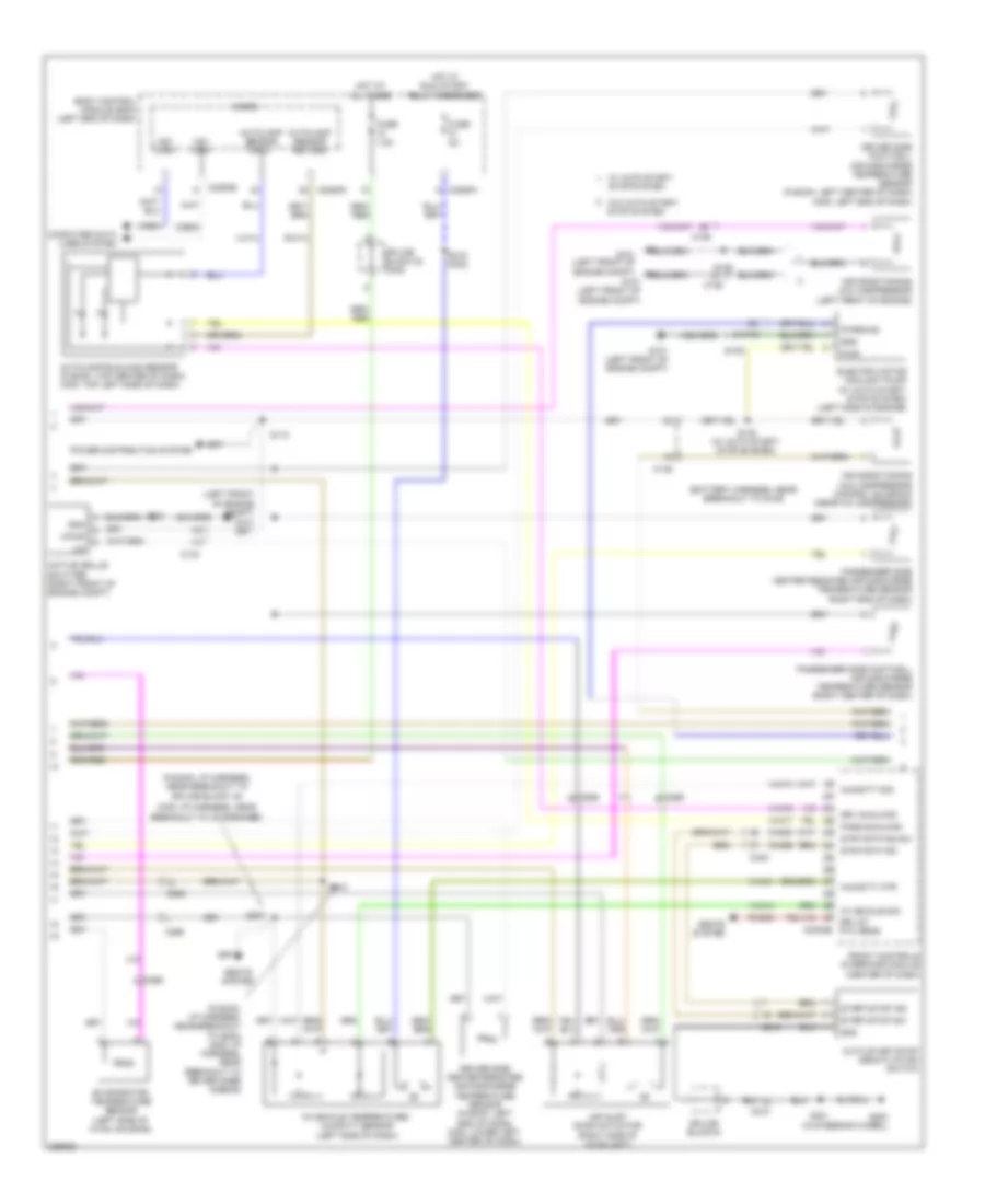
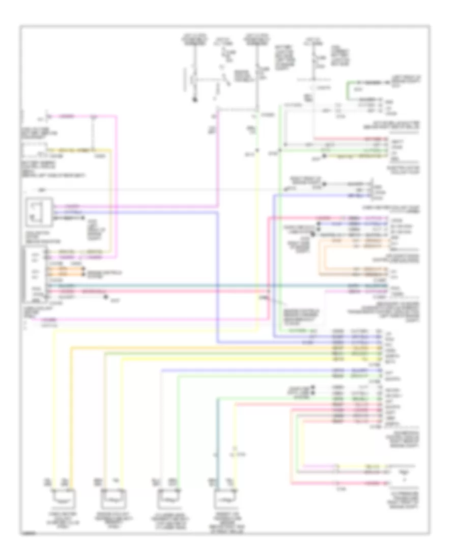
Automatic A/C Wiring Diagram, Except Hybrid (1 of 3) for Ford Fusion Titanium 2013

List of elements for Automatic A/C Wiring Diagram, Except Hybrid (1 of 3) for Ford Fusion Titanium 2013:
- (a/c jumper harness, near breakout to blower motor)
- (center of dash)
- (right side of dash) g202
- (right side of hvac unit) blower motor
- 40a
- A/c clutch relay
- Air distribution door actuator (left side of hvac unit)
- Battery junction box (bjb) (left side of engine compt)
- Blower control
- Blower motor control module (right side of hvac unit)
- Blower motor relay
- Blower relay
- C1035a
- C1035b
- C219
- C2402a
- C2402b
- C265
- C268
- C297a
- C297b
- Ch123
- Ch201
- Ch202
- Ch203
- Ch206
- Ch207
- Ch208
- Ch211
- Ch212
- Ch213
- Ch237
- Ch238
- Ch239
- Ch402
- Chs02
- Chs07
- Computer data lines system
- Crd02
- Defogger system
- Defrost request
- Driver temperature door actuator (left side of hvac unit)
- Drv frt snsr 1
- Drv frt snsr 2
- Drv heater feed
- Evap
- Feedback
- Front controls interface module
- Fuse
- Fuse 10a
- Fuse 15a
- Fuse 20a
- G101 (left front of engine compt)
- G202 (right side of dash)
- Gd216
- Gnd
- Hot at all times
- Hot w/ pcm power relay energized
- Lh111
- Motor+
- Motor-
- Ms can+
- Ms can-
- Pass frt snsr 1
- Pass frt snsr 2
- Pass heater feed
- Pass st ntc sens
- Passenger temperature door actuator (right side of hvac unit)
- Red
- Rh111
- Rh301
- Rhs10
- S202
- S203 (a/c jumper harness, near breakout to blower motor)
- S210
- Sbb65
- Sbp12
- Seats system
- Sig rtn
- Vbatt
- Vdb06
- Vdb07
- Vh101
- Vh301
- Vh406
- Vh409
- Vh410
- Vh411
- Vh412
- Vref
- W/ heated seats
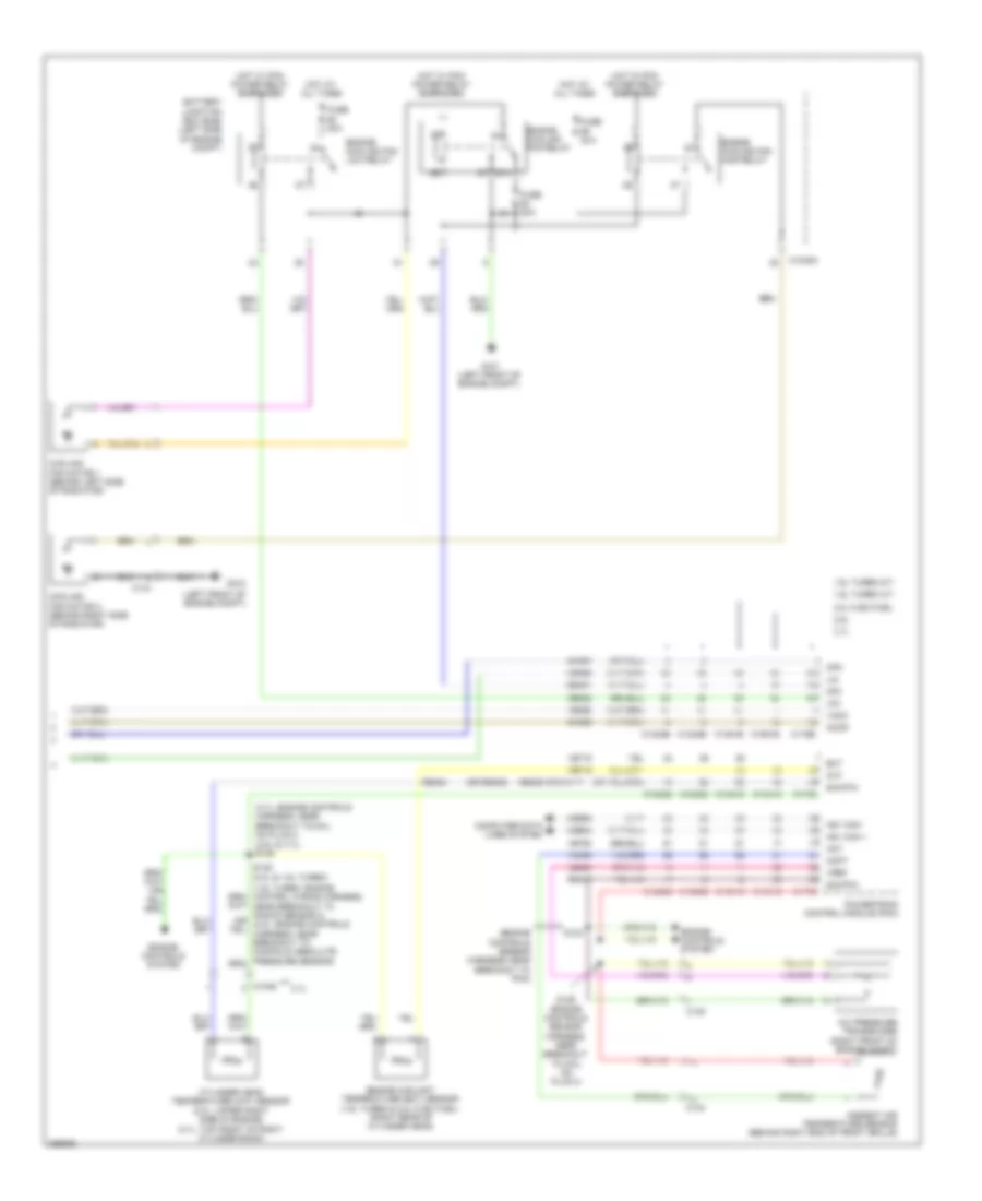
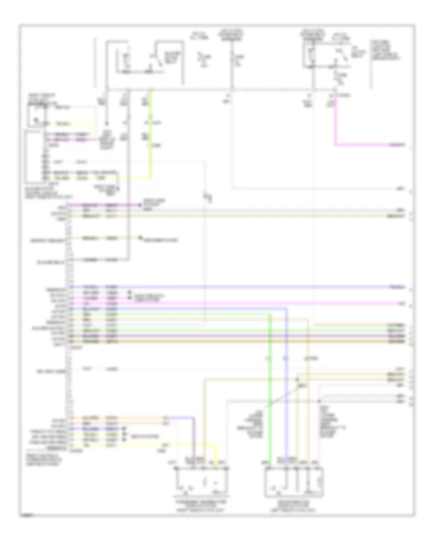
Automatic A/C Wiring Diagram, Except Hybrid (2 of 3) for Ford Fusion Titanium 2013
List of elements for Automatic A/C Wiring Diagram, Except Hybrid (2 of 3) for Ford Fusion Titanium 2013:
- (battery harness, near breakout to g109)
- (center of dash)
- (fusion: i/p harness, near breakout to g202) (mkz: i/p harness, near breakout to driver knee airbag)
- (fusion: i/p harness, near breakout to splice block 19)
- (left front of engine compt)
- (mkz: i/p harness, near
- Active grille shutter (right front of engine compt)
- Air conditioning (a/c) compressor (left front of engine)
- Air conditioning (a/c) compressor control solenoid (near a/c compressor)
- Air inlet door actuator (right side of hvac unit)
- Auto start/stop deactivation switch
- Autolamp sensor input
- Autolamp sensor return
- Autolamp/sunload sensor (fusion: top center of dash) (mkz: top left side of dash)
- Body control module (bcm) (left end of dash)
- Breakout to i/p speaker)
- C134
- C146
- C210
- C2280b
- C2280g
- C2280h
- C2402b
- C265
- C340
- Ch253
- Ch469
- Computer data lines system
- Driver side center register air discharge temperature sensor (fusion: left end of dash) (mkz: lower left center of dash)
- Driver side footwell air discharge temperature sensor (fusion: left center of dash) (mkz: left end of dash)
- Drv st ntc sens
- Drv sunload
- Electric motor coolant pump (w/ auto start/ stop system) (left side of engine)
- Evaporator temperature sensor (left side of hvac housing)
- Front controls interface module
- Fuse 5a
- Fuse 7.5a
- G101
- G101 (left front of engine compt)
- G200 (in steering wheel)
- Gnd
- Hot at all times
- Hot w/ run/ start relay energized
- Hs1 can+
- Hs1 can-
- Humidity mtr
- Humidity sig
- In vehicle sig
- In-vehicle temperature/ humidity sensor (left side of dash)
- Lin
- Micro
- Pass sunload
- Passenger side center register air discharge temperature sensor (right end of dash)
- Passenger side footwell air discharge temperature sensor (right center of dash)
- Power distribution system
- Pwr
- Pwr/diag
- Rhs05
- Rlf14
- S101
- S110
- S139
- S140 (w/ auto start/ stop system)
- S207
- S213
- S219 (mkz)
- S301
- Seats system
- Splice block 22 (mkz)
- Splice block 6
- Start/stop ind
- Start/stop sw
- Stop system
- Strt/stp dis sw
- Strt/stp ind
- Vdb04
- Vdb05
- Vh413
- Vh414
- Vh416
- Vh417
- Vha31
- Vlf14
- Vpwr
- W/ auto start/
- W/o auto start/ stop system
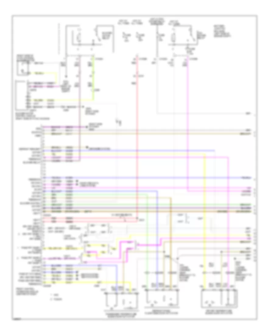
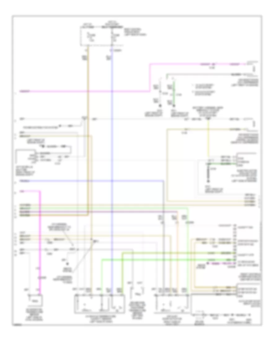
Automatic A/C Wiring Diagram, Except Hybrid (3 of 3) for Ford Fusion Titanium 2013
List of elements for Automatic A/C Wiring Diagram, Except Hybrid (3 of 3) for Ford Fusion Titanium 2013:
- (2.5l & 3.7l) s146
- (3.7l: engine controls harness, near breakout to coil on plug 3)
- (3.7l: top front of right cylinder bank)
- (engine controls sensor harness, near breakout to pcm)
- (left front of engine compt)
- (or re405)
- 1.6l turbo a/t
- 1.6l turbo m/t
- 2.0l flex fuel
- 2.5l
- 3.7l
- 87a
- A/c pressure transducer (right front of engine compt)
- Aat
- Accr
- Acpt
- Ambient air temperature sensor (behind right end of front grille)
- Battery junction box (bjb) (left side of engine compt)
- C1035a
- C1046
- C1232b
- C1232e
- C134
- C1381b
- C1381e
- C144
- C145
- C1551b
- C1551e
- C175b
- C175e
- Ce202
- Cec01
- Ch302
- Ch307
- Cht
- Computer data lines system
- Cooling fan motor 1 (behind left side of radiator)
- Cooling fan motor 2 (behind right side of radiator)
- Cpc
- Cylinder head temperature (cht) sensor (2.0l: upper right side of engine)
- Ect
- Engine controls system
- Engine coolant temperature (ect) sensor (1.6l turbo & 2.0l flex fuel) (right rear of cylinder head)
- Engine cooling fan high relay
- Engine cooling fan low relay
- Engine cooling fan relay
- Fuse 20a
- Fuse 30a
- G100
- G101 (left front of engine compt)
- Hfc
- Hot at all times
- Hot w/ pcm power relay energized
- Hs1 can +
- Hs1 can -
- Le424
- Lfc
- Lin
- Powertrain control module (pcm)
- Re405
- Re407
- Re454
- S126 (engine controls sensor harness, near breakout to coil on plug 3)
- S133
- S149 (2.0l & 1.6l turbo)
- Sig rtn
- Vacc
- Vdb04
- Vdb05
- Vdn06
- Ve462
- Ve712
- Ve716
- Ve750
- Vh433
- Vref
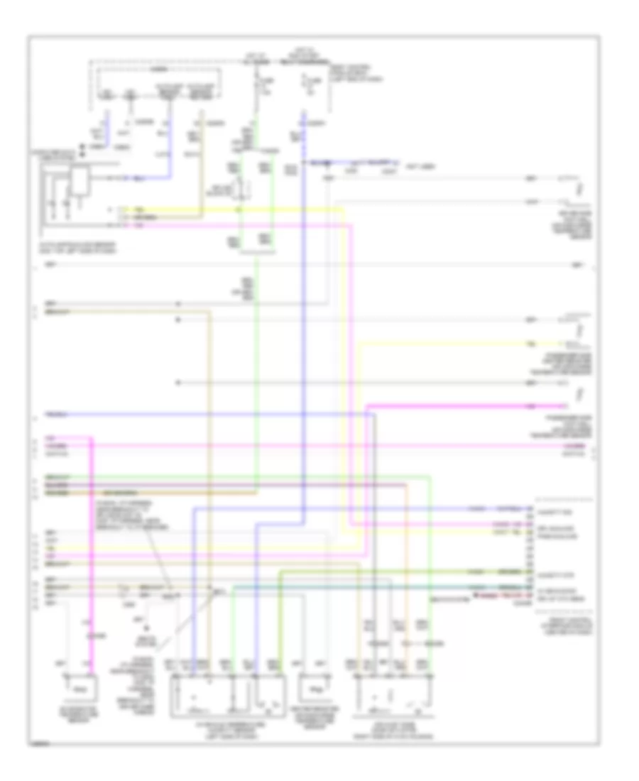
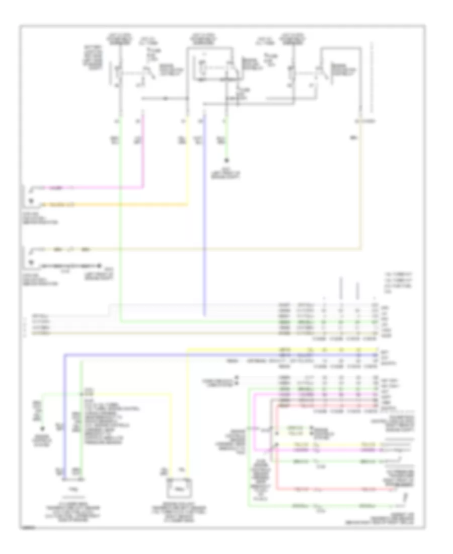
Automatic A/C Wiring Diagram, Hybrid (1 of 3) for Ford Fusion Titanium 2013
List of elements for Automatic A/C Wiring Diagram, Hybrid (1 of 3) for Ford Fusion Titanium 2013:
- (a/c jumper harness, near breakout to blower motor)
- (or vh410)
- (right side of dash)
- (right side of dash) g202
- (right side of hvac housing) blower motor
- 40a
- Battery junction box (bjb) (left side of engine compt)
- Blower control
- Blower motor control module (right side of hvac housing)
- Blower motor relay
- Blower relay
- C1035a
- C1035b
- C219
- C2402a
- C2402b
- C265
- C268
- C297a
- C297b
- Ch123
- Ch201
- Ch202
- Ch203
- Ch206
- Ch207
- Ch208
- Ch211
- Ch212
- Ch213
- Ch237
- Ch238
- Ch239
- Ch402
- Chs02
- Chs07
- Computer data lines system
- Crd02
- Defogger system
- Defrost request
- Defrost/panel/ floor mode door actuator
- Driver temperature blend door actuator
- Drv frt snsr 1 (or drv frt snsr 2)
- Drv frt snsr 1 drv frt snsr
- Drv heater feed
- Evap
- Feedback
- Front control interface module (center of dash)
- Fuse
- Fuse 10a
- Fuse 15a
- Fuse 20a
- Fusion
- G101 (left front of engine compt)
- G202
- Gd216
- Gnd
- Hot at all times
- Hot w/ pcm power relay energized
- Lh111
- Mkz
- Motor+
- Motor-
- Ms can+
- Ms can-
- Pass frt snsr 1
- Pass frt snsr 2
- Pass heater feed
- Pass st ntc sens
- Passenger temperature blend door actuator
- Red
- Rh111
- Rh301
- Rhs10
- S202
- S203 (a/c jumper harness, near breakout to blower motor)
- S210
- Sbb65
- Sbp12
- Seats system seats system
- Sig rtn
- Tcm power relay
- Vbatt
- Vdb06
- Vdb07
- Vh101
- Vh301
- Vh406
- Vh409
- Vh410 (or vh409)
- Vh411 (or vh412)
- Vh412 (or vh411)
- Vref
- W/ heated seats
Automatic A/C Wiring Diagram, Hybrid (2 of 3) for Ford Fusion Titanium 2013
List of elements for Automatic A/C Wiring Diagram, Hybrid (2 of 3) for Ford Fusion Titanium 2013:
- (fusion: i/p harness, near breakout to g202) (mkz: i/p harness, near breakout to driver knee airbag)
- (fusion: i/p harness, near breakout to splice block 19) (mkz: i/p harness, near breakout to i/p speaker)
- (not used)
- Air inlet mode door actuator (right side of hvac housing)
- Autolamp sensor input
- Autolamp sensor return
- Autolamp/sunload sensor (mkz: top left side of dash)
- Body control module (bcm) (left end of dash)
- C2280b
- C2280g
- C2280h
- C2402b
- C248
- C265
- C3047
- Center register air discharge temperature sensor
- Computer data lines system
- Driver side footwell air discharge temperature sensor
- Drv st ntc sens
- Drv sunload
- Evaporator temperature sensor
- Front control interface module (center of dash)
- Fuse 5a
- Fuse 7.5a
- Fusion
- Hot at all times
- Hot w/ run/ start relay energized
- Hs1 can+
- Hs1 can-
- Humidity mtr
- Humidity sig
- In vehicle sig
- In-vehicle temperature/ humidity sensor (left side of dash)
- Micro
- Mkz
- Pass sunload
- Passenger side center register air discharge temperature sensor
- Passenger side footwell air discharge temperature sensor
- Rhs05
- Rlf14
- S207
- S213
- S219 (mkz)
- Seats system
- Splice block 22
- Vdb04
- Vdb05
- Vh413
- Vh414
- Vh416
- Vh417
- Vha31
- Vlf14
Automatic A/C Wiring Diagram, Hybrid (3 of 3) for Ford Fusion Titanium 2013
List of elements for Automatic A/C Wiring Diagram, Hybrid (3 of 3) for Ford Fusion Titanium 2013:
- (engine controls sensor harness, near breakout to g100)
- (left front of engine compt)
- (left front of engine compt) g101
- (right front of engine compt) g106
- (right side of engine compt)
- (top center of cylinder head)
- A/c pressure transducer (right front of engine compt)
- Aat
- Acpt
- Active grille shutter (behind right end of grille)
- Air conditioning control module (accm)
- Ambient air temperature sensor (behind right end of front grille)
- Battery energy control module (becm) (behind left side of rear seat)
- Battery junction box (bjb) (left side of engine compt)
- C1026
- C1035a
- C134
- C145
- C1458a
- C1458f
- C146
- C1617k
- C175b
- C175e
- C1815a
- C1815b
- C1815c
- C4000
- C4002
- C4816b
- Cabin coolant heater (phev)
- Cabin heater coolant diverter valve (phev)
- Cabin heater coolant pump (phev)
- Cbb54
- Ce167
- Ce316
- Ch307
- Chp01
- Cht
- Computer data lines system
- Cooling fan motor (behind radiator)
- Cyb03
- Cylinder head temperature (ect)
- Ect2
- Electric motor coolant pump
- Engine controls system
- Engine coolant temperature (ect) sensor 2 (phev)
- Engine cooling fan relay
- Ev hs can+
- Ev hs can-
- Fcv
- Fuse 20a
- Fuse 275a
- Fuse 30a
- G100
- G105
- G107
- Gd113
- Gnd
- Hcso
- High current battery junction box (bjb)
- High voltage battery service disconnect
- Hot at all times
- Hot w/ pcm power relay energized
- Hs can +
- Hs can -
- Hv+
- Hv-
- Le423
- Lin
- Powertrain control module (right rear of engine compt)
- Pwm
- Re141
- Re405
- Re407
- S101
- S108
- S110
- S115
- S145
- Secondary on board diagnostic module (sobdmc)/ transmission control module (tcm) (left side of engine compt)
- Sig rtn
- Sigrtn
- Tcmrc
- Vbatt
- Vdb04
- Vdb05
- Vdn06
- Ve712
- Ve716
- Ve750
- Vec03
- Verf
- Vh433
- Vpwr
Manual A/C Wiring Diagram (1 of 3) for Ford Fusion Titanium 2013
List of elements for Manual A/C Wiring Diagram (1 of 3) for Ford Fusion Titanium 2013:
- (a/c jumper harness, near breakout to blower motor)
- (right side of dash) g202
- (right side of hvac unit) blower motor
- 40a
- A/c clutch relay
- Air distribution door actuator (left side of hvac unit)
- Battery junction box (bjb) (left side of engine compt)
- Blower control
- Blower motor control module (right side of hvac unit)
- Blower motor relay
- Blower relay
- C1035a
- C219
- C2402a
- C2402b
- C265
- C268
- C297a
- C297b
- Ch123
- Ch201
- Ch202
- Ch203
- Ch206
- Ch207
- Ch208
- Ch211
- Ch212
- Ch213
- Ch402
- Chs02
- Chs07
- Computer data lines system
- Crd02
- Defogger system
- Defrost request
- Drv frnt snsr
- Drv heater feed
- Evap
- Feedback
- Front controls interface module (center of dash)
- Fuse
- Fuse 10a
- Fuse 15a
- G101 (left front of engine compt)
- Gd216
- Gnd
- Hot at all times
- Hot w/ pcm power relay energized
- Lh111
- Motor+
- Motor-
- Ms can+
- Ms can-
- Pass heater feed
- Pass st ntc sens
- Passenger temperature door actuator (right side of hvac unit)
- Rh111
- Rh301
- Rhs10
- S202
- S203 (a/c jumper harness, near breakout to blower motor)
- Sbp12
- Seats system
- Sig rtn
- Vbatt
- Vdb06
- Vdb07
- Vh101
- Vh301
- Vh406
- Vh409
- Vref
Manual A/C Wiring Diagram (2 of 3) for Ford Fusion Titanium 2013
List of elements for Manual A/C Wiring Diagram (2 of 3) for Ford Fusion Titanium 2013:
- (battery harness, near breakout to g109) (w/ auto start/ stop system) s140
- (i/p harness, near breakout to g202)
- (i/p harness, near breakout to splice block 19)
- (left front of engine compt)
- (right side of hvac unit)
- Active grille shutter (right front of engine compt)
- Air conditioning (a/c) compressor (left front of engine)
- Air conditioning (a/c) compressor control solenoid (near a/c compressor)
- Air inlet door actuator
- Auto start/stop deactivation switch
- Body control module (bcm) (left end of dash)
- C134
- C146
- C210
- C2280h
- C2402b
- C265
- C340
- Ch253
- Ch469
- Driver side footwell air discharge temperature sensor (left end of dash)
- Drv st ntc sens
- Electric motor coolant pump (w/ auto start/stop system) (left side of engine)
- Evaporator temperature sensor (left side of hvac housing)
- Front controls interface module (center of dash)
- Fuse 5a
- Fuse 7.5a
- G101 (left front of engine compt)
- G200 (in steering wheel)
- Gnd
- Hot at all times
- Hot w/ run/ start relay energized
- Humidity mtr
- Humidity sig
- In vehicle sig
- In-vehicle temperature/ humidity sensor (left side of dash)
- Lin
- Power distribution system
- Pwr
- Pwr/diag
- Rhs05
- S101
- S110
- S139
- S207
- S213
- S301
- Seats system
- Splice block 6
- Start/stop ind
- Start/stop sw
- Strt/stp dis sw
- Strt/stp ind
- Vh413
- Vh414
- Vha31
- Vpwr
- W/ auto start/ stop system
- W/o auto start/ stop system
Manual A/C Wiring Diagram (3 of 3) for Ford Fusion Titanium 2013
List of elements for Manual A/C Wiring Diagram (3 of 3) for Ford Fusion Titanium 2013:
- (2.5l) s146
- (engine controls sensor harness, near breakout to pcm)
- (left front of engine compt)
- (or re405)
- 1.6l turbo a/t
- 1.6l turbo m/t
- 2.0l flex fuel
- 2.5l
- 87a
- A/c pressure transducer (right front of engine compt)
- Aat
- Accr
- Acpt
- Ambient air temperature sensor (behind right end of front grille)
- Battery junction box (bjb) (left side of engine compt)
- C1035a
- C1232b
- C1232e
- C134
- C1381b
- C1381e
- C144
- C145
- C1551b
- C1551e
- Ce202
- Cec01
- Ch302
- Ch307
- Cht
- Computer data lines system
- Cooling fan motor 1 (behind radiator)
- Cooling fan motor 2 (behind radiator)
- Cpc
- Cylinder head temperature (cht) sensor (2.0l flex fuel & 2.5l) (2.0l flex fuel: upper right side of engine)
- Ect
- Engine controls system
- Engine coolant temperature (ect) sensor (1.6l turbo & 2.0l flex fuel) (right rear of cylinder head)
- Engine cooling fan high relay
- Engine cooling fan low relay
- Engine cooling fan relay
- Fuse 20a
- Fuse 30a
- G100
- G101 (left front of engine compt)
- Hfc
- Hot at all times
- Hot w/ pcm power relay energized
- Hs1 can +
- Hs1 can -
- Le424
- Lfc
- Lin
- Near breakout to knock sensor 2) (2.0l: engine controls harness, near breakout to manifold absolute pressure sensor)
- Powertrain control module (pcm) (right rear of engine compt)
- Re405
- Re407
- Re454
- S126 (engine controls sensor harness, near breakout to coil on plug 3)
- S133
- Sig rtn
- Vacc
- Vdb04
- Vdb05
- Vdn06
- Ve462
- Ve712
- Ve716
- Ve750
- Vh433
- Vref