AIR CONDITIONING
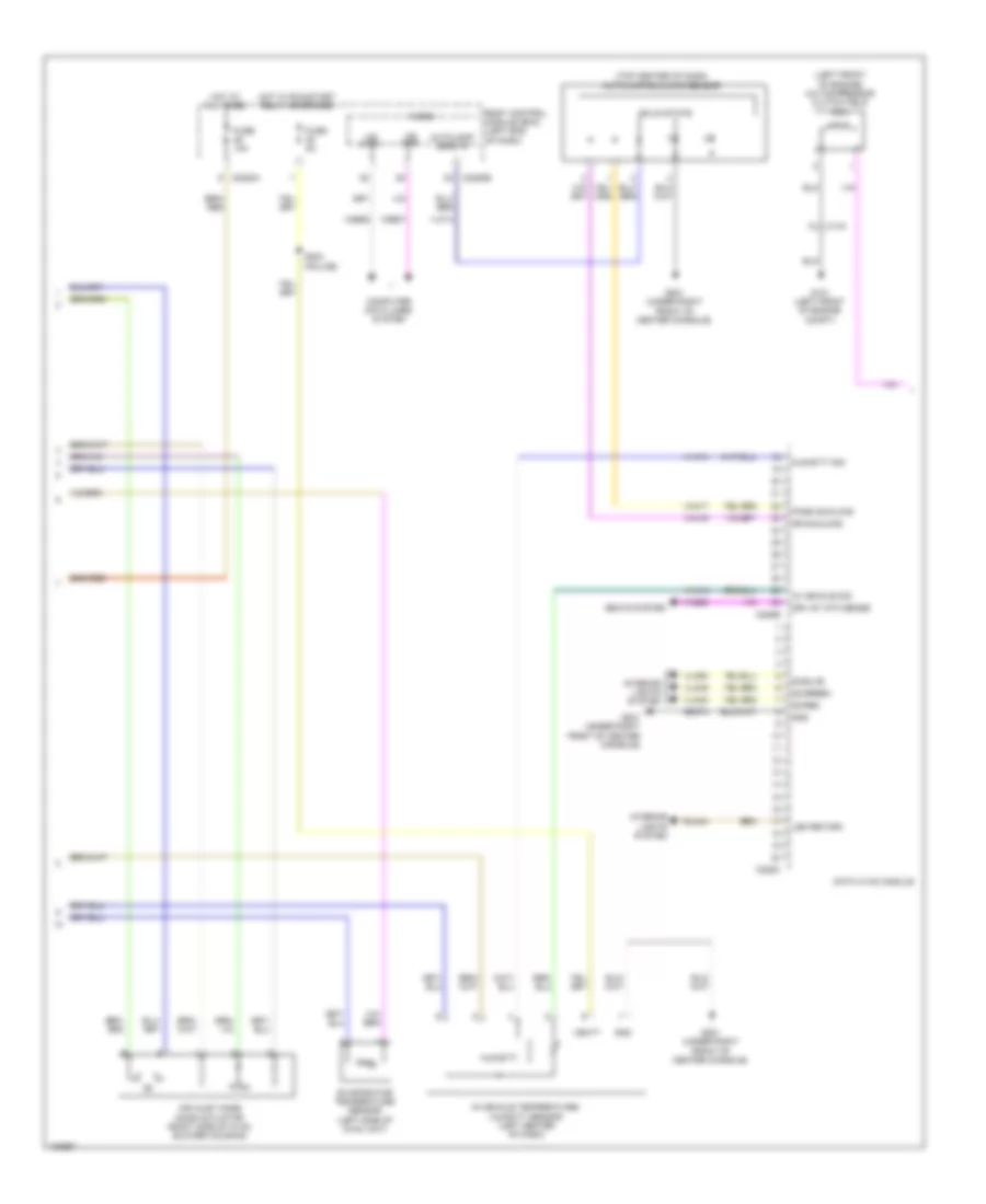
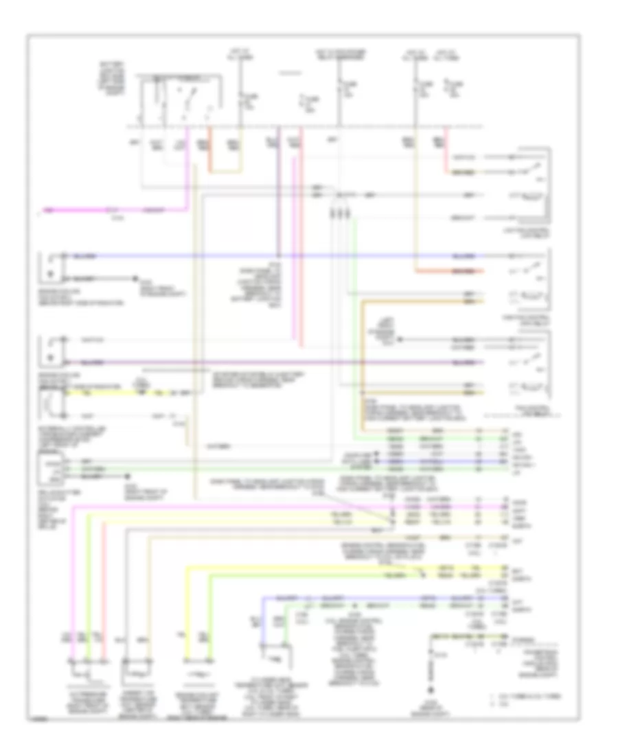
Automatic A/C Wiring Diagram (1 of 3) for Ford Police Interceptor Sedan 2014

List of elements for Automatic A/C Wiring Diagram (1 of 3) for Ford Police Interceptor Sedan 2014:
- (dash panel to headlamp junction wiring harness, near breakout to blower motor) s202
- (dash panel to headlamp junction wiring harness, near breakout to evaporator temperature sensor)
- (on blower motor) blower motor speed control
- (right side of hvac unit) blower motor
- Battery junction box (bjb) (left side of engine compt)
- Blower motor relay
- Blwr rly
- C210
- C213
- C228a
- C228b
- Ch122
- Ch123
- Ch207
- Ch208
- Ch212
- Ch213
- Ch228
- Ch229
- Ch238
- Ch239
- Chs02
- Chs07
- Computer data lines system
- Datc hvac module
- Defogger system
- Defrost req
- Defrost/panel/ floor mode door actuator (upper left side of hvac unit)
- Drv heater feed
- Evap
- Feedback
- Fuse 28
- Fuse 30a
- Fuse 40a
- Fuse 5a
- G200 (under left front of center console)
- G201 (under right front of center console)
- Gd374
- Gnd
- Hot at all times
- Hot w/ run/start relay energized
- Left side temperature blend door actuator (lower left side of hvac unit)
- Lh111
- Motor +
- Motor -
- Ms can +
- Ms can -
- Pass heater feed
- Pass st ntc sense
- Rh111
- Right side temperature blend door actuator (upper right side of hvac unit)
- S147
- S203
- S209
- S210
- Sbb28
- Sbp46
- Seats system
- Sig return
- Var blwr ctrl
- Vbatt
- Vdb06
- Vdb07
- Vh101
- Vh406
- Vh436
- Vh438
- Vh440
- Vh441
- Vhs27
- Vref
- W/ heated seats
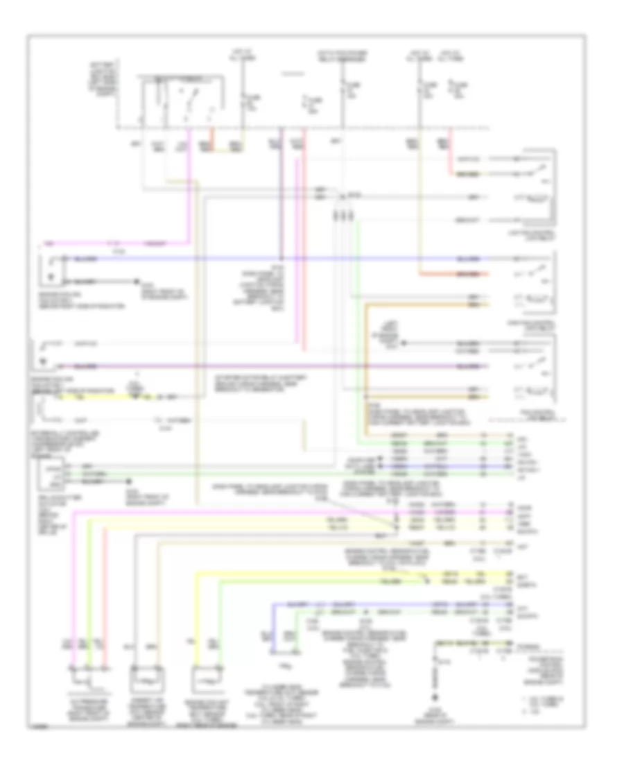
Automatic A/C Wiring Diagram (2 of 3) for Ford Police Interceptor Sedan 2014
List of elements for Automatic A/C Wiring Diagram (2 of 3) for Ford Police Interceptor Sedan 2014:
- (left front of engine) a/c compressor clutch field coil
- (top center of dash) autolamp/sunload sensor
- Air inlet mode door actuator (right side of hvac blower housing)
- Autolamp sens in
- Body control module (bcm) (left end of dash)
- C144
- C2280a
- C2280b
- C228b
- C228c
- Computer data lines system
- Datc hvac module
- Dr sunload
- Drv st ntc sense
- Evaporator temperature sensor (left side of hvac unit)
- Fuse 10a
- Fuse 5a
- G101 (left front of engine compt)
- G201 (under right front of center console)
- Gd374
- Gnd
- Hot at all times
- Hot w/ run/start relay energized
- Humidity
- Humidity sig
- In vehicle sig
- In-vehicle temperature/ humidity sensor (left center of dash)
- Interior lights system
- Led return
- Micro
- Ms can+
- Ms can-
- Pass sunload
- Rln44
- S204 (police)
- Seats system
- Solid state
- Vbatt
- Vdb06
- Vdb07
- Vh413
- Vh414
- Vh416
- Vh417
- Vhs26
- Vlf14
- Vln48
- Vln49
- Vln50
- Z2-green
- Z2-red
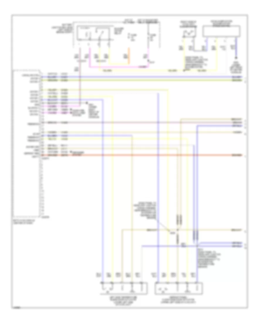
Automatic A/C Wiring Diagram (3 of 3) for Ford Police Interceptor Sedan 2014
List of elements for Automatic A/C Wiring Diagram (3 of 3) for Ford Police Interceptor Sedan 2014:
- (2.0l turbo)
- (2.0l turbo) s108
- (3.5l turbo)
- (3.5l)
- (dash panel to headlamp junction wiring harness, near breakout to g102) s125
- (dash panel to headlamp junction wiring harness, near breakout to high current battery junction box) s148
- (engine control sensor & fuel charge wiring harness, near breakout to coil on plug 2) s113
- (left front of engine compt) g101
- (starter motor relay & battery ground wiring harness, near breakout to generator)
- 2.0l turbo & 3.5l turbo
- 3.5l
- A/c clutch relay
- A/c pressure transducer (right front of engine compt)
- Aat
- Accr
- Acpt
- Ambient air temperature (aat) sensor (center of engine compt)
- Battery junction box (bjb) (left side of engine compt)
- C1381b
- C1381e
- C144
- C175b
- C175e
- C192
- Cec07
- Cec08
- Ch302
- Cht
- Computer data lines system
- Cylinder head temperature (cht) sensor (3.5l & 3.5l turbo) (3.5l: front of right cylinder head) (3.5l turbo: rear of right cylinder head)
- Ect
- Engine coolant temperature (ect) sensor (2.0l turbo) (right rear of engine)
- Engine cooling fan motor 1 (behind left side of radiator)
- Engine cooling fan motor 2 (behind right side of radiator)
- Externally controlled variable displacement compressor (evdc) (left front of engine)
- Fan control (fc) relay
- Fuse 10a
- Fuse 15a
- Fuse 25a
- Fuse 40a
- G100 (right front of engine compt)
- G100 (right front of of engine compt)
- G105 (rear of engine compt)
- Gd113
- Gnd
- Grille shutter actuator (3.5l) (behind right center of grille)
- Hfc
- High fan control (hfc) relay
- Hot at all times
- Hot w/ pcm power relay energized
- Hs can +
- Hs can -
- Le424
- Lfc
- Lin
- Low fan control (lfc) relay
- Powertrain control module (pcm) (rear of engine compt)
- Pwrgnd
- Re405
- Re407
- Re454
- S109 (3.5l: engine control sensor & fuel charge wiring harness, near breakout to fuel injector 2) (3.5l turbo: engine control sensor & fuel charge wiring harness, near breakout to c123)
- S116
- S119
- S142 (dash panel to headlamp junction wiring harness, near breakout to battery junction box)
- S155 (dash panel to headlamp junction wiring harness, near breakout to high current battery junction box)
- Sig rtn
- Sigrtn
- Vacc
- Vdb04
- Vdb05
- Vdn06
- Ve462
- Ve712
- Ve716
- Vh407
- Vh433
- Vpwr
- Vref
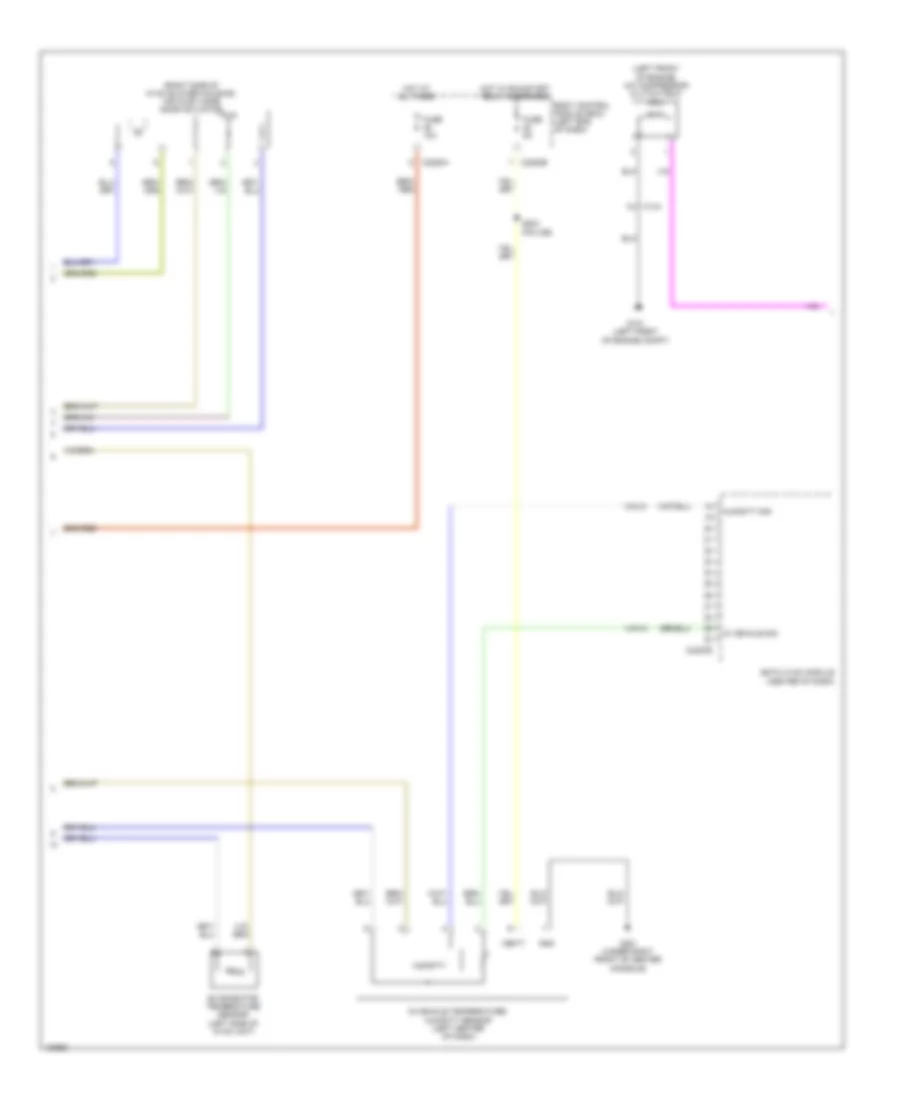
Manual A/C Wiring Diagram (1 of 3) for Ford Police Interceptor Sedan 2014
List of elements for Manual A/C Wiring Diagram (1 of 3) for Ford Police Interceptor Sedan 2014:
- (dash panel to headlamp junction wiring harness, near breakout to blower motor) s202
- (dash panel to headlamp junction wiring harness, near breakout to evaporator temperature sensor)
- (on blower motor) blower motor speed control
- (right side of hvac unit) blower motor
- Battery junction box (bjb) (left side of engine compt)
- Blower motor relay
- Blwr rly
- C210
- C2357a
- C2357b
- Ch122
- Ch123
- Ch207
- Ch208
- Ch228
- Ch229
- Ch238
- Ch239
- Computer data lines system
- Defogger system
- Defrost req
- Defrost/panel/ floor mode door actuator (upper left side of hvac unit)
- Emtc hvac module (center of dash)
- Evap
- Feedback
- Fuse 40a
- Fuse 5a
- G200 (under left front of center console)
- G201 (under right front of center console)
- Gd374
- Gnd
- Hot at all times
- Hot w/ run/start relay energized
- Left side temperature blend door actuator (lower left side of hvac unit)
- Lh111
- Motor +
- Motor -
- Ms can +
- Ms can -
- Rh111
- S147
- S209
- S210 (dash panel to headlamp junction wiring harness, near breakout to evaporator temperature sensor)
- Sbp46
- Sig return
- Var blwr ctrl
- Vbatt
- Vdb06
- Vdb07
- Vh101
- Vh406
- Vh436
- Vh438
- Vh440
- Vref
Manual A/C Wiring Diagram (2 of 3) for Ford Police Interceptor Sedan 2014
List of elements for Manual A/C Wiring Diagram (2 of 3) for Ford Police Interceptor Sedan 2014:
- (left front of engine) a/c compressor clutch field coil
- (right side of hvac blower housing) air inlet mode door actuator
- Body control module (bcm) (left end of dash)
- C144
- C2280a
- C2280b
- C2357b
- Emtc hvac module (center of dash)
- Evaporator temperature sensor (left side of hvac unit)
- Fuse 10a
- Fuse 5a
- G101 (left front of engine compt)
- G201 (under right front of center console)
- Gnd
- Hot at all times
- Hot w/ run/start relay energized
- Humidity
- Humidity sig
- In vehicle sig
- In-vehicle temperature/ humidity sensor (left center of dash)
- S204 (police)
- Vbatt
- Vh413
- Vh414
Manual A/C Wiring Diagram (3 of 3) for Ford Police Interceptor Sedan 2014
List of elements for Manual A/C Wiring Diagram (3 of 3) for Ford Police Interceptor Sedan 2014:
- (2.0l turbo)
- (2.0l turbo) s108
- (3.5l turbo)
- (3.5l)
- (dash panel to headlamp junction wiring harness, near breakout to g102) s125
- (dash panel to headlamp junction wiring harness, near breakout to high current battery junction box) s148
- (engine control sensor & fuel charge wiring harness, near breakout to coil on plug 2) s113
- (left front of engine compt) g101
- (starter motor relay & battery ground wiring harness, near breakout to generator)
- 2.0l turbo & 3.5l turbo
- 3.5l
- A/c clutch relay
- A/c pressure transducer (right front of engine compt)
- Aat
- Accr
- Acpt
- Ambient air temperature (aat) sensor (center of engine compt)
- Battery junction box (bjb) (left side of engine compt)
- C1381b
- C1381e
- C144
- C175b
- C175e
- C192
- Cec07
- Cec08
- Ch302
- Cht
- Computer data lines system
- Cylinder head temperature (cht) sensor (3.5l & 3.5l turbo) (3.5l: front of right cylinder head) (3.5l turbo: rear of right cylinder head)
- Ect
- Engine coolant temperature (ect) sensor (2.0l turbo) (right rear of engine)
- Engine cooling fan motor 1 (behind left side of radiator)
- Engine cooling fan motor 2 (behind right side of radiator)
- Externally controlled variable displacement compressor (evdc) (left front of engine)
- Fan control (fc) relay
- Fuse 10a
- Fuse 15a
- Fuse 25a
- Fuse 40a
- G100 (right front of engine compt)
- G105 (rear of engine compt)
- Gd113
- Gnd
- Grille shutter actuator (3.5l) (behind right center of grille)
- Hfc
- High fan control (hfc) relay
- Hot at all times
- Hot w/ pcm power relay energized
- Hs can +
- Hs can -
- Le424
- Lfc
- Lin
- Low fan control (lfc) relay
- Powertrain control module (pcm) (rear of engine compt)
- Pwrgnd
- Re405
- Re407
- Re454
- S109 (3.5l: engine control sensor & fuel charge wiring harness, near breakout to fuel injector 2) (3.5l turbo: engine control sensor & fuel charge wiring harness, near breakout to c123)
- S116
- S119
- S142 (dash panel to headlamp junction wiring harness, near breakout to battery junction box)
- S155 (dash panel to headlamp junction wiring harness, near breakout to high current battery junction box)
- Sigrtn
- Vacc
- Vdb04
- Vdb05
- Vdn06
- Ve462
- Ve712
- Ve716
- Vh407
- Vh433
- Vpwr
- Vref