AIR CONDITIONING
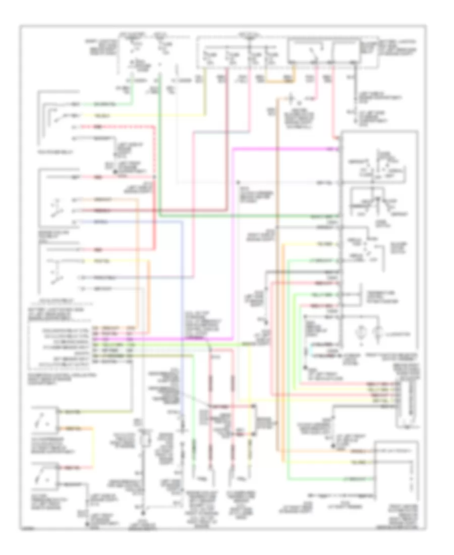
Heater Wiring Diagram for Ford Ranger 2006

List of elements for Heater Wiring Diagram for Ford Ranger 2006:
Manual A/C Wiring Diagram for Ford Ranger 2006
List of elements for Manual A/C Wiring Diagram for Ford Ranger 2006:
 English
Heater Wiring Diagram for Ford Ranger 2006
List of elements for Heater Wiring Diagram for Ford Ranger 2006:
Manual A/C Wiring Diagram for Ford Ranger 2006
List of elements for Manual A/C Wiring Diagram for Ford Ranger 2006: