AIR CONDITIONING
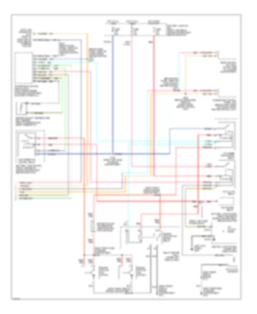
Automatic A/C Wiring Diagram (1 of 2) for Ford Taurus LX 2001

List of elements for Automatic A/C Wiring Diagram (1 of 2) for Ford Taurus LX 2001:
- (behind center of instrument cluster) g202
- (right rear side of engine compartment) g123
- (right rear side of engine) s113
- A/c clutch cycling pressure switch (right front of engine compartment, behind right headlamp)
- A/c demand sig
- Air temp door
- Ambient air temperature sensor (behind right side of front bumper)
- Ambient temp
- Battery
- Blend dr act pwr
- Blower motor relay
- Blower mtr input
- Blower rly ctrl
- C201b
- C270b
- C271a
- C271b
- Center of instrument cluster) s205
- Central junction box (under left side of dash)
- Data bus
- Dual pressure switch (behind a/c compressor)
- Front blower motor (right side of dash, below glove box)
- Front blower motor speed controller (behind center of dash, near hvac unit)
- Fuse 208 40a
- Fuse 216 15a
- Fuse 228 10a
- G202 (behind center of instrument cluster)
- Generic electronic module (gem) (under left side of dash)
- Ground
- Hot at all times
- Hot in run
- Ignition
- In car temp sens
- In vehicle temperature sensor
- Integrated control panel (icp) (behind dash, near a/c-heater control unit)
- Photo cell & ampifier (top right side of dash)
- Remote climate control (rcc) module (behind right side of dash, behind glove box)
- Scp bus (+)
- Scp bus (-)
- Sensor signal rtn
- Solid state
- Sunload sensor
- Tan
- Temperature blend door actuator (behind instrument cluster, under dash panel)
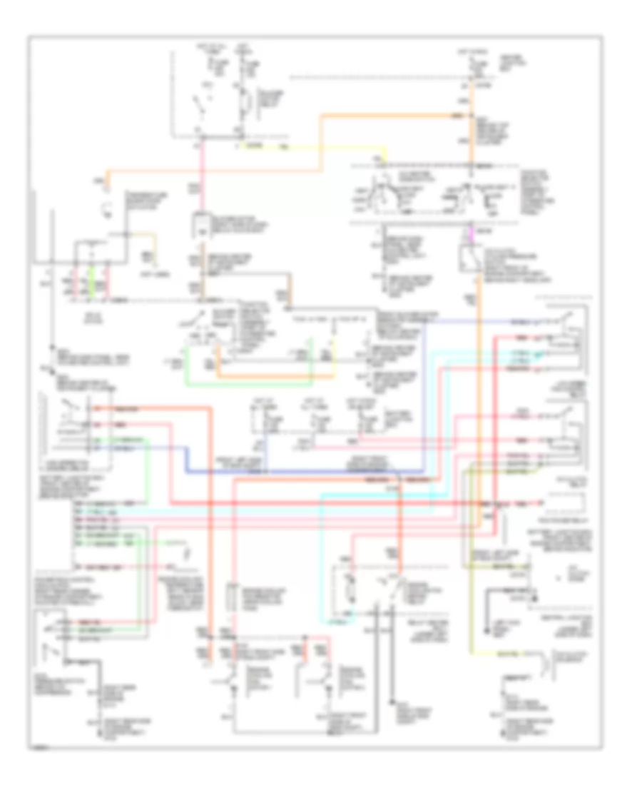
Automatic A/C Wiring Diagram (2 of 2) for Ford Taurus LX 2001
List of elements for Automatic A/C Wiring Diagram (2 of 2) for Ford Taurus LX 2001:
- (behind dash panel, near air conditioning/ heater control unit) s219
- (behind dash, panel, near air conditioning/ heater control unit) s217
- (front left side of eng compt)
- (left kick panel) g200
- (right front side of engine compartment) g101
- (right front side of engine compartment) s141
- (right front side of engine compartment) s142
- (right front side of engine compartment) s146
- (right rear side of engine compartment) g123
- (right rear side of engine) s113
- 87a
- A/c clutch diode
- A/c clutch relay
- A/c clutch solenoid
- Battery junction box (front center of engine compartment, behind radiator
- Battery junction box (front center of engine compartment, behind radiator)
- C270a
- C270c
- Central junction box (under left side of dash)
- Data link connector (dlc) (partial) (mounted on dash, below steering column)
- Engine coolant temperature (ect) sensor (rear of engine block, near thermostat)
- Engine cooling fan brake relay
- Engine cooling fan motor 1
- Engine cooling fan motor 2
- Engine cooling fan resistor (near electric cooling fans)
- Fuse 10a
- Fuse 15a
- Fuse 40a
- High speed fan control relay
- Hot at all times
- Hot in run or start
- Integrated control panel (icp) (behind dash, near air conditioning/ heater control unit)
- Low speed fan control relay
- Pcm power relay
- Powertrain control module (pcm) (right rear corner of engine compartment, mounted in firewall)
- Rear control unit (rcu) (in left side of luggage compartment)
- Red
- Relay center box 1 (under left side of dash)
- S138 (front left side of engine compartment)
- S140
- S218 (behind dash, panel, near air conditioning/ heater control unit)
- S220 (behind dash panel, near air conditioning/ heater control unit)
- Tan
Manual A/C Wiring Diagram for Ford Taurus LX 2001
List of elements for Manual A/C Wiring Diagram for Ford Taurus LX 2001:
- (behind center of instrument cluster) g202
- (behind center of instrument cluster) s201
- (front left side of eng compt)
- (front left side of eng compt) s138
- (left kick panel) g200
- (not used)
- (right front side of engine compartment)
- (right rear side of engine compartment) g123
- (right rear side of engine) s113
- 87a
- A/c clutch cycling pressure switch (right front of engine compartment, behind right headlamp)
- A/c clutch diode
- A/c clutch relay
- A/c clutch solenoid
- A/c heater mode switch
- A/c-heater control unit) s203
- Battery junction box
- Battery junction box (front center of engine compartment, behind radiator)
- Blower motor (right side of dash, below glove box)
- Blower motor relay
- Blower switch
- C270a
- C270b
- C270c
- C294a
- C294b
- C294c
- Center junction box
- Central junction box (under left side of dash)
- Cluster) s202
- Def
- Dual pressure switch (behind a/c compressor)
- Engine coolant temperature (ect) sensor (rear of eng block, near thermostat)
- Engine cooling fan brake relay
- Engine cooling fan motor 1
- Engine cooling fan motor 2
- Engine cooling fan resistor (near cooling fans)
- Floor
- Floor/vent
- Front blower motor resistor assembly (in dash, below center of glove box)
- Function selector switch assembly (part of integrated control panel)
- Fuse 10a
- Fuse 15a
- Fuse 40a
- G101 (right front side of eng compt)
- G202 (behind center of instrument cluster)
- High
- High speed fan control relay
- Hot at all times
- Hot in run
- Hot in run or start
- Low
- Low speed fan control relay
- Max
- Med med
- Mix
- Norm
- Of engine compartment) g123
- Off
- Pcm power relay
- Powertrain control module (pcm) (right rear corner, of engine compartment, mounted in firewall)
- Red
- Relay center box 1 (under left side of dash)
- S113 (right rear side of engine)
- S140
- S146
- S203 (behind dash panel, near a/c-heater control unit)
- S207 (behind top center of instrument cluster)
- Solid state
- Temperature blend door actuator
- Vent