AIR CONDITIONING
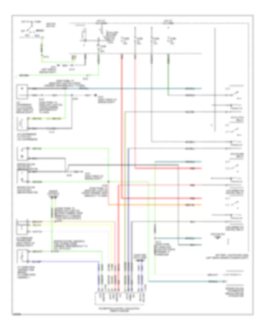
Manual A/C Wiring Diagram (1 of 2) for Ford Transit Connect XLT Premium 2013

List of elements for Manual A/C Wiring Diagram (1 of 2) for Ford Transit Connect XLT Premium 2013:
Manual A/C Wiring Diagram (2 of 2) for Ford Transit Connect XLT Premium 2013
List of elements for Manual A/C Wiring Diagram (2 of 2) for Ford Transit Connect XLT Premium 2013: