AIR CONDITIONING
2.3L
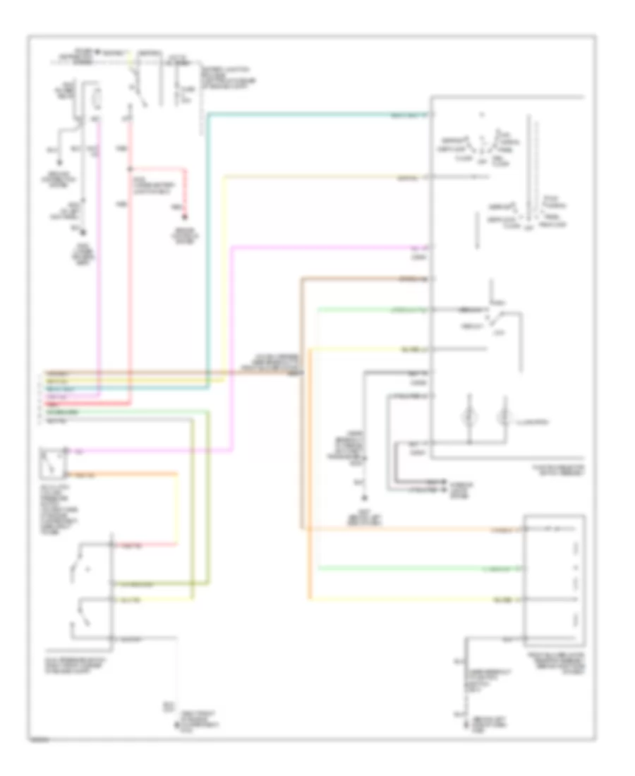
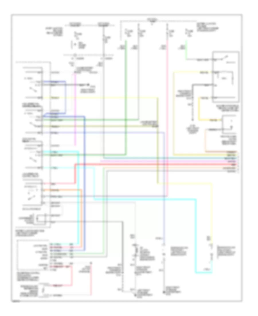
2.3L, Manual A/C Wiring Diagram, Except Hybrid (1 of 2) for Mercury Mariner Hybrid 2006

List of elements for 2.3L, Manual A/C Wiring Diagram, Except Hybrid (1 of 2) for Mercury Mariner Hybrid 2006:
- (left front of engine compartment) g105
- (right front corner of engine compt) s114
- (right front of engine compartment) g102
- (under battery junction box) s127
- (under battery junction box) s128
- (under battery junction box) s131
- A/c clutch relay
- A/c clutch solenoid (at right front corner of engine compt)
- A/c compressor clutch diode
- Accr
- Accs
- Acpsw
- Battery junction box (bjb) (left front corner of engine compt)
- Blower motor relay (behind lower left center of dash)
- C175b
- C175e
- C2280a
- C2280b
- Cht
- Cooling fan ctrl
- Cooling fan relay
- Cylinder head temperature sensor (top of engine, on valve cover)
- Engine cooling fan motor 1 (left front of engine compt)
- Engine cooling fan motor 2 (right front of engine compt)
- Front blower motor (behind right side of dash)
- Fuse 15a
- Fuse 2a
- Fuse 40a
- Fuse 5a
- G105 (left front of engine compt)
- Hi fan ctrl
- High speed fan control relay 1
- Hot at all times
- Hot in run or start
- Low fan ctrl
- Low speed fan control relay
- Pcm power diode
- Powertrain control module (pcm) (rear center of firewall)
- Red
- S109 (at rear top of engine)
- S144 (under battery junction box)
- Sigrtne
- Smart junction box (sjb) (below center of dash)
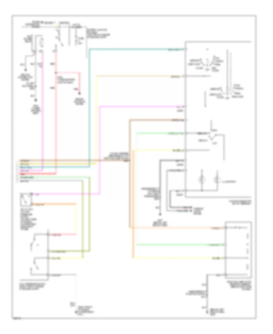
2.3L, Manual A/C Wiring Diagram, Except Hybrid (2 of 2) for Mercury Mariner Hybrid 2006
List of elements for 2.3L, Manual A/C Wiring Diagram, Except Hybrid (2 of 2) for Mercury Mariner Hybrid 2006:
- (behind left side of dash) g206
- (in main harness, near breakout to front blower motor) s200
- (near breakout to ignition switch) s214
- (near breakout to passive anti-theft transceiver) s208
- (right front of engine compartment) g103
- A/c clutch cycling pressure switch (on right side of engine compartment, near strut tower)
- Battery junction box (bjb) (left front corner of engine compt)
- C294a
- C294b
- C294c
- Def/floor
- Defrost
- Dual pressure switch (right front corner of engine compt)
- Engine controls system
- Floor
- Front blower motor resistor assembly (behind right side of dash)
- Function selector switch assembly
- Fuse 30a
- G207 (behind left side of dash)
- G300 (under driver's seat)
- Ground distribution system
- High
- Hot at all times
- Illumination
- Interior lights system
- Low
- Max
- Medium 1
- Medium 2
- Normal
- Off
- Pan/ floor
- Pan/floor
- Panel
- Pcm power relay
- Power distribution system
- Red
- S129 (under battery junction box)
- S332 (at left kick panel)
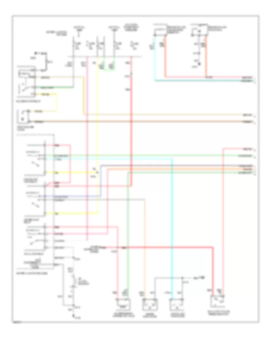
2.3L, Manual A/C Wiring Diagram, Hybrid (1 of 3) for Mercury Mariner Hybrid 2006
List of elements for 2.3L, Manual A/C Wiring Diagram, Hybrid (1 of 3) for Mercury Mariner Hybrid 2006:
- A/c clutch cycling pressure switch
- A/c clutch relay
- A/c clutch solenoid
- A/c compressor clutch diode
- A/c refrigerant distribution valve
- Battery junction box (bjb)
- Blower motor relay
- Engine cooling fan dropping resistor 1
- Engine cooling fan motor 2
- Front blower motor
- Fuse 10a
- Fuse 15a
- Fuse 30a
- Fuse 40a
- G103
- G206
- Heater pump motor
- Heater pump relay
- Hot at all times
- Hot w/ pcm power relay energized
- M/e coolant pump motor
- M/e coolant pump relay
- Power distribution system
- Red
- S112
- S119
- S120
- S129
- S149
- S151
- S152
- S212
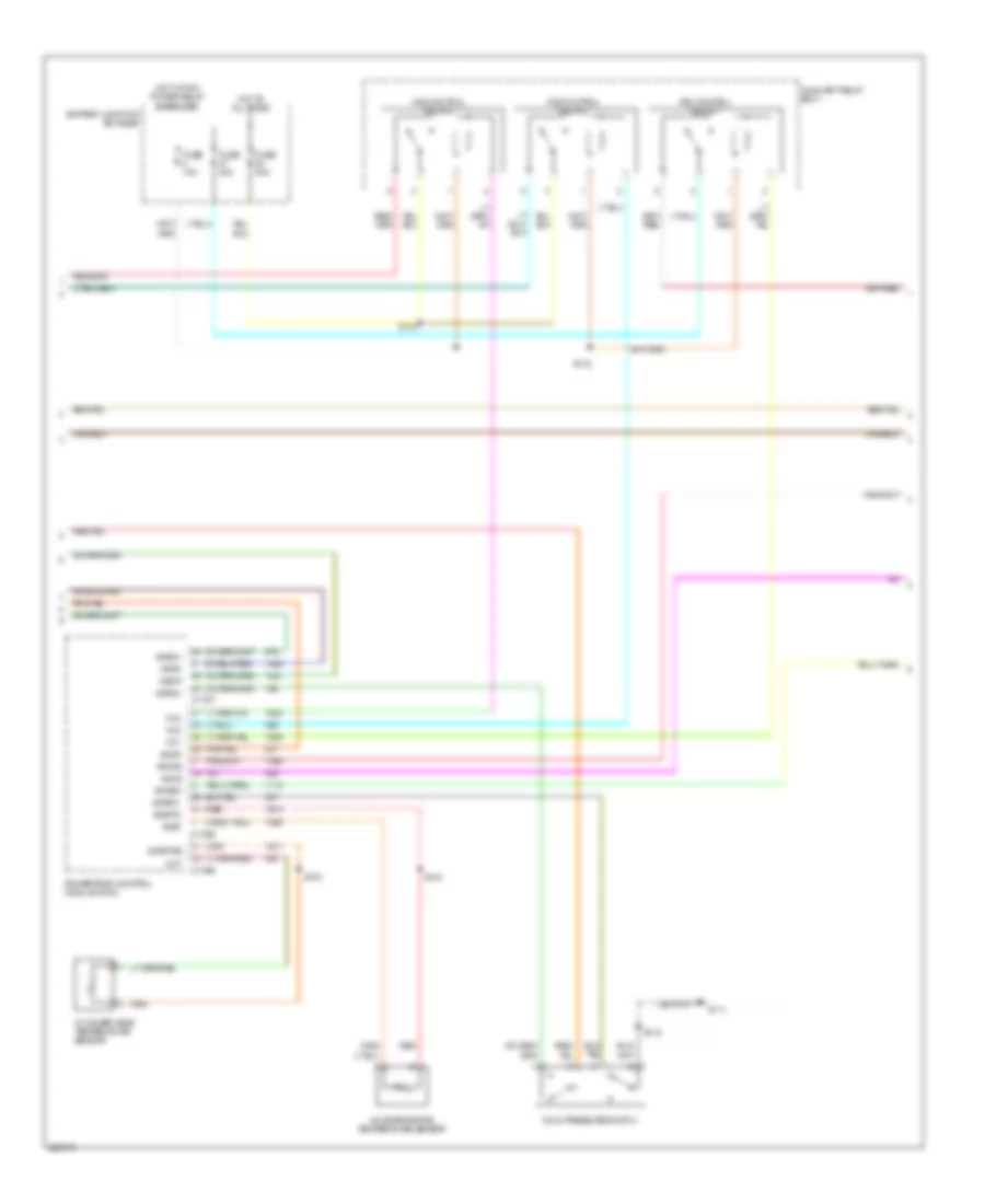
2.3L, Manual A/C Wiring Diagram, Hybrid (2 of 3) for Mercury Mariner Hybrid 2006
List of elements for 2.3L, Manual A/C Wiring Diagram, Hybrid (2 of 3) for Mercury Mariner Hybrid 2006:
- A/c evaporative temperature sensor
- Accr
- Accs
- Acet
- Acfds
- Acpsw
- Acrdv
- Acrsw
- Auxiliary relay box 1
- Battery junction box (bjb)
- C175b
- C175e
- C175t
- Cht
- Cylinder head temperature sensor
- Dual pressure switch
- Fan control relay 1
- Fan control relay 2
- Fan control relay 3
- Fc1
- Fc2
- Fc3
- Fuse 10a
- Fuse 40a
- G111
- Hot at all times
- Hot w/ pcm power relay energized
- Hpcr
- Mecp
- Powertrain control module (pcm)
- Red
- S103
- S116
- S118
- S134
- S144
- Sigrtn
- Sigrtne
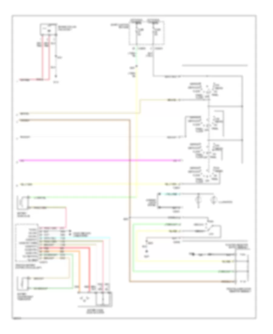
2.3L, Manual A/C Wiring Diagram, Hybrid (3 of 3) for Mercury Mariner Hybrid 2006
List of elements for 2.3L, Manual A/C Wiring Diagram, Hybrid (3 of 3) for Mercury Mariner Hybrid 2006:
- A/c
- Battery compartment thermistor
- Battery mode door actuator
- Battery zone valve
- C2280a
- C2280d
- C294a
- C294b
- C294c
- C4227a
- Computer data lines system
- Def/floor
- Defrost
- Engine cooling fan motor 1
- Floor
- Front blower motor resistor assembly
- Function selector switch assembly
- Fuse 5a
- G110
- G206
- G207
- High
- Hot in run or start
- Hs can+
- Hs can-
- Illumination
- Interior lights system
- Low
- Max
- Medium 1
- Medium 2
- Mode mtr+
- Mode mtr-
- Mode pot wiper
- Mode pot+
- Mode pot-
- Off
- Panel
- Panel/ floor
- Panel/ floor off
- Recirc
- Red
- S121
- S122
- S200
- S208
- S214
- S251
- Smart junction box (sjb)
- Traction battery control module (left)
- Txv sol
- Txv temp
- Txv temp rtn
3.0L
3.0L, Manual A/C Wiring Diagram, Except Hybrid (1 of 2) for Mercury Mariner Hybrid 2006
List of elements for 3.0L, Manual A/C Wiring Diagram, Except Hybrid (1 of 2) for Mercury Mariner Hybrid 2006:
- (left front of engine compartment) g105
- (right front corner of engine compt) s131
- (right front of eng compt)
- (right front of engine compartment) g102
- (right front of engine compartment) s114
- (under battery junction box) s128
- (under battery junction box) s145
- 87a
- A/c clutch relay
- A/c clutch solenoid (at right front side of engine compt)
- A/c compressor clutch diode
- Accr
- Accs
- Acpsw
- Battery junction box (bjb) (left front corner of engine compt)
- Blower motor relay (behind lower left center of dash)
- C175b
- C175e
- C2280a
- C2280b
- Cooling fan relay
- Ect
- Engine coolant temperature sensor (rear of engine, in water outlet)
- Engine cooling fan motor 1 (left front of engine compt)
- Engine cooling fan motor 2 (right front of engine compt)
- Front blower motor (behind right side of dash)
- Fuse 15a
- Fuse 2a
- Fuse 40a
- Fuse 50a
- Fuse 5a
- G102
- G105 (left front of engine compt)
- Hi fan ctrl
- High speed fan control relay 2
- Hot at all times
- Hot in run or start
- Low fan ctrl
- Low speed fan control relay
- Pcm power diode
- Powertrain control module (pcm) (in recess on upper center of firewall)
- Red
- S154 (on top of engine)
- Sigrtne
- Smart junction box (sjb) (below center of dash)
3.0L, Manual A/C Wiring Diagram, Except Hybrid (2 of 2) for Mercury Mariner Hybrid 2006
List of elements for 3.0L, Manual A/C Wiring Diagram, Except Hybrid (2 of 2) for Mercury Mariner Hybrid 2006:
- (at left kick panel) s332
- (behind left side of dash) g206
- (in main harness, near breakout to front blower motor) s200
- (near breakout to igntion switch) s214
- (near breakout to passive anti-theft transceiver) s208
- (right front of engine compartment) g103
- A/c clutch cycling pressure switch (on right side of engine compartment, near strut tower)
- Battery junction box (bjb) (left front corner of engine compt)
- C294a
- C294b
- C294c
- Def/floor
- Defrost
- Dual pressure switch (right front corner of engine compt)
- Engine controls system
- Floor
- Front blower motor resistor assembly (behind right side of dash)
- Function selector switch assembly
- Fuse 30a
- G207 (behind left side of dash)
- G300 (under driver's seat)
- Ground distribution system
- High
- Hot at all times
- Illumination
- Interior lights system
- Low
- Max
- Medium 1
- Medium 2
- Normal
- Off
- Pan/ floor
- Pan/floor
- Panel
- Pcm power relay
- Power distribution system
- Red
- S129 (under battery junction box)