ANTI-LOCK BRAKES
Anti-lock Brake Wiring Diagrams for Ford Crown Victoria 1997
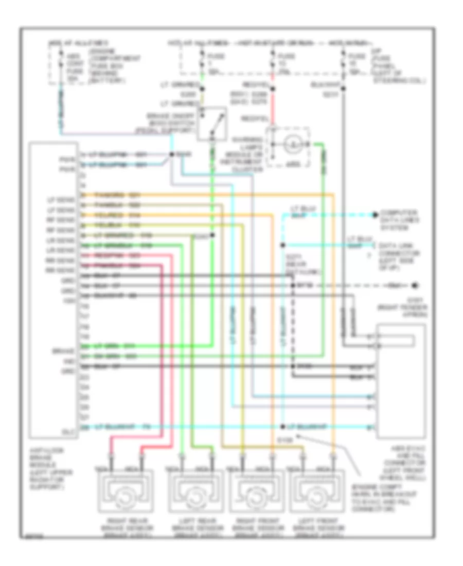
List of elements for Anti-lock Brake Wiring Diagrams for Ford Crown Victoria 1997:
- (engine compt harn, in breakout to evac and fill connector)
- (ngv) (gas)
- (right fender apron)
- Abs
- Abs cont fuse 30a
- Abs evac and fill connector (left front wheel well)
- Anti-lock brake module (left upper radiator support)
- Brake
- Brake on/off (boo) switch (pedal support)
- Computer data lines system
- Data link connector (left side of i/p)
- Dlc
- Engine compartment fuse box (behind battery)
- Fuse 10a
- Fuse 15a
- G101
- Grd
- Hot at all times
- Hot in run
- Hot in start or run
- I/p fuse panel (left of steering col.)
- Ign
- Ind
- Left front brake sensor (brake ass'y)
- Left rear brake sensor (brake ass'y)
- Lf sens
- Lr sens
- Nca
- Pwr
- Red/pnk
- Rf sens
- Right front brake sensor (brake ass'y)
- Right rear brake sensor (brake ass'y)
- Rr sens
- S112
- S136
- S146
- S231
- S243
- S265
- S271 (near datalink)
- S299 s276
- Warning lamps module or instrument cluster
 English