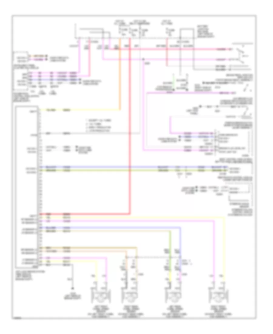
ANTI-LOCK BRAKES
Anti-lock Brakes Wiring Diagram for Ford Escape SE 2014
List of elements for Anti-lock Brakes Wiring Diagram for Ford Escape SE 2014:
- (top rear of transmission) g104
- 1.6l turbo
- 2.0l turbo
- 2.5l
- Anti-lock brake system (abs) module (left rear of engine compt)
- Battery junction box (bjb) (left side of engine compt)
- Body control module (bcm) (bottom right center of dash)
- Bpp
- Bps
- Brake fluid level sw
- Brake pedal position (bpp) switch (top of brake pedal assembly)
- C1035c
- C1381b
- C1551b
- C175b
- C210
- C226a
- C2280a
- C2280c
- C3053
- C310b
- C405
- C406
- Cbp03
- Ccb08
- Ces09
- Cmc19
- Cmc25
- Computer data lines system
- Early production
- Except 1.6l turbo
- Fuse 30a
- Fuse 40a
- Fuse 5a
- G103 (right side of engine compt)
- G105 (left rear of engine compt)
- G205 (left kick panel)
- Gd122
- Gnd
- Hot at all times
- Hot w/ ign relay energized
- Hs can +
- Hs can -
- Hs can2 +
- Hs can2 -
- Instrument panel cluster (ipc) module
- Late production
- Left front wheel speed sensor (on left front wheel hub assembly)
- Left rear wheel speed sensor (on left rear wheel hub assembly)
- Lf sensor hi
- Lf sensor lo
- Low brake fluid warning indicator switch (on brake fluid reservoir)
- Lr sensor hi
- Lr sensor lo
- Micro
- Ms can +
- Ms can -
- Nca
- Park brake sw
- Parking brake switch (base of parking brake lever assembly)
- Powertrain control module (pcm) (left side of engine compt)
- Rca17
- Rca18
- Rca19
- Rca20
- Red
- Restraints control module (under center console)
- Rf sensor hi
- Rf sensor lo
- Right front wheel speed sensor (on right front wheel hub assembly)
- Right rear wheel speed sensor (on right rear wheel hub assembly)
- Rr sensor hi
- Rr sensor lo
- S125
- S134
- S221
- S250
- Sbb25
- Sbb26
- Steering angle sensor
- Steering column control module (in steering column)
- Stop light sw
- Vbatt
- Vca03
- Vca04
- Vca05
- Vca06
- Vca23
- Vca24
- Vdb04
- Vdb05
- Vpwr
 English