ANTI-LOCK BRAKES
Anti-lock Brake Wiring Diagrams for Ford Explorer Sport Trac 2001
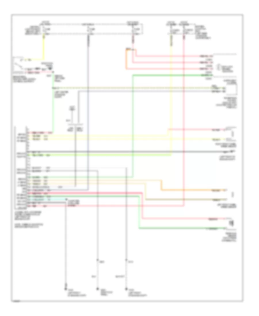
List of elements for Anti-lock Brake Wiring Diagrams for Ford Explorer Sport Trac 2001:
- (behind left dash panel)
- (left center of engine compt)
- (left front of engine compt)
- (left front of engine compt)
- (not used)
- (right kick panel) g203
- 4-wheel anti-lock brake system (4wabs) module (left front of engine compt)
- Abs ind
- Anti-lock brakes indicator
- Battery junction box (left rear of engine compartment)
- Bpp sw
- Brake pedal position (bpp) switch (on pedal support)
- C220a
- C220b
- C220c
- Central junction box (behind left side of dash)
- Computer data lines system
- Cpu fd
- Differential)
- Early prod
- Fuse 10a
- Fuse 28 30a
- Fuse 6 50a
- Fuse 7.5a
- G100
- G203 (right kick panel)
- Ground
- Hot at all times
- Hot in run
- Hot in run or start
- Ign
- Instrument cluster
- Iso link
- Late prod
- Left front wheel speed sensor
- Lf sens
- Note: there is a shorting bar across pins 8 & 16
- Ohms
- Powertrain control module (pcm) (mounted through firewall)
- Pump fd
- Rear axle sensor (top of rear
- Red
- Red/pnk
- Rf sens
- Right front wheel speed sensor
- Rr sens
- S117
- S118
- S203
- S218
- S227
- Vss
 English