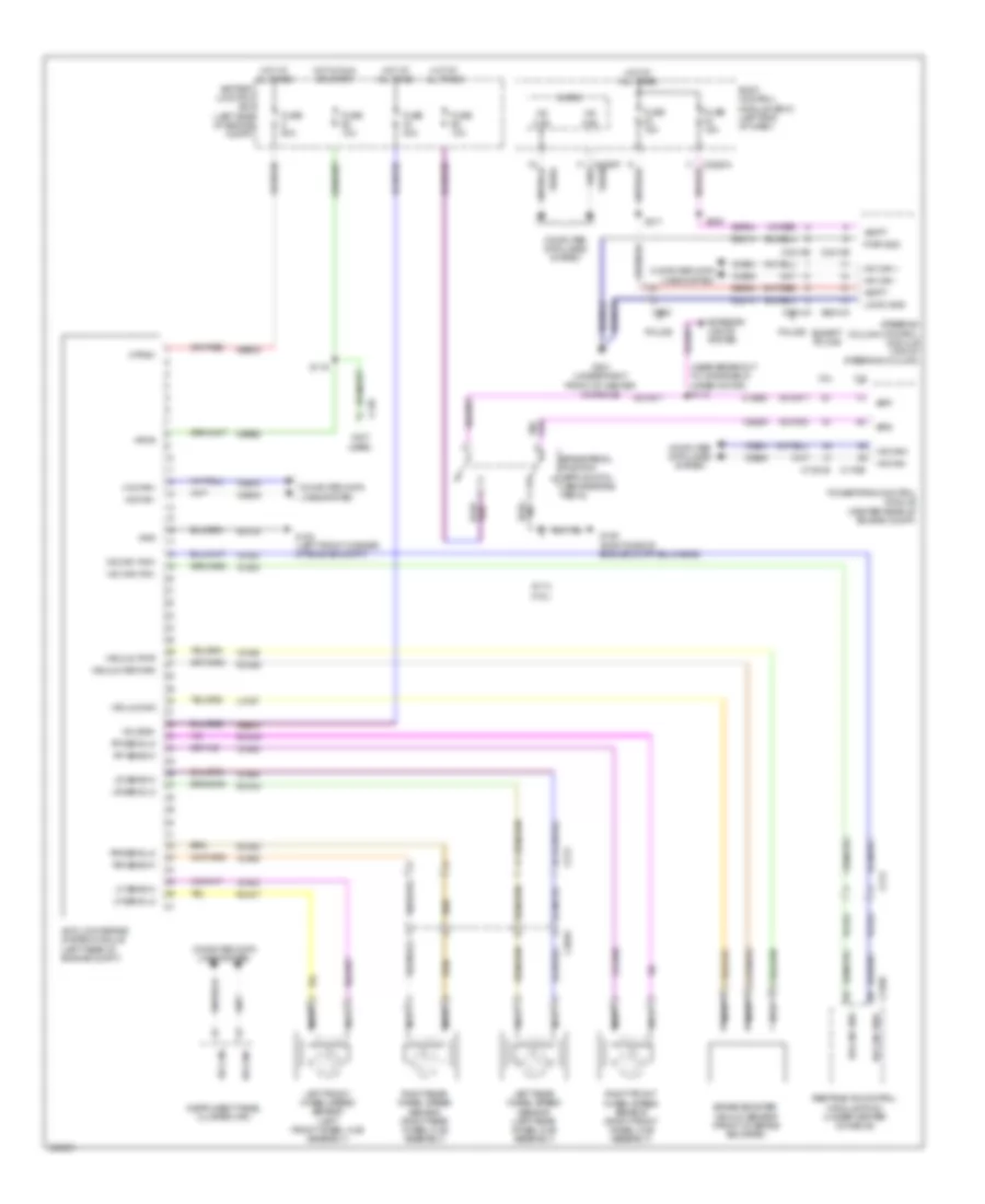
ANTI-LOCK BRAKES
Anti-lock Brakes Wiring Diagram for Ford Explorer XLT 2013
List of elements for Anti-lock Brakes Wiring Diagram for Ford Explorer XLT 2013:
- (near breakout to windshield wiper motor) s112
- (not used)
- 2.0l
- 3.5l
- Anti-lock brake system module (left rear of engine compt)
- Battery junction box (left side of engine compt)
- Body control module (bcm) (left end of dash)
- Bpp
- Bps
- Brake booster vacuum sensor (front of brake booster)
- Brake pedal position (bpp) switch (above brake pedal)
- C1381b
- C139
- C175b
- C213
- C2280a
- C2280f vdb05
- C2414a
- C2414b
- C263
- C3049
- C310b
- Cbb92
- Ccb08
- Ces09
- Computer data lines system
- Except police
- Exterior lights system
- Fuse 10a
- Fuse 15a
- Fuse 40a
- Fuse 50a
- G103 (left front corner of engine compt)
- G106 (right side of engine compt bulkhead)
- G201 (under right front of center console)
- Gd120
- Gd214
- Gnd
- Hot at all times
- Hot in run or start
- Hs can +
- Hs can -
- Hs can yaw+
- Hs can yaw-
- Hs can+
- Hs can-
- Instrument panel cluster (ipc)
- Lca37
- Left front wheel speed sensor (left front wheel hub assembly)
- Left rear wheel speed sensor (left rear wheel hub assembly)
- Lf sens hi
- Lf sens lo
- Logic gnd
- Lr sens hi
- Lr sens lo
- Micro
- Mtr b+
- Nca
- Police
- Powertrain control module (center rear of engine compt)
- Pwr gnd
- Rca17
- Rca18
- Rca19
- Rca20
- Rca36
- Restraints control module (rcm) (under center console)
- Rf sens hi
- Rf sens lo
- Right front wheel speed sensor (right front wheel hub assembly)
- Right rear wheel speed sensor (right rear wheel hub assembly)
- Rr sens hi
- Rr sens lo
- S114 (3.5l)
- S119
- S205
- S211
- Sbb05
- Sbb43
- Sbp23
- Sbp24
- Steering column control module (top of steering column)
- Vacuum pwr
- Vacuum return
- Vacuum sig
- Valve b+
- Vbatt
- Vca03
- Vca04
- Vca05
- Vca06
- Vca23
- Vca24
- Vca36
- Vdb04
- Vdb05
- Vpwr
 English