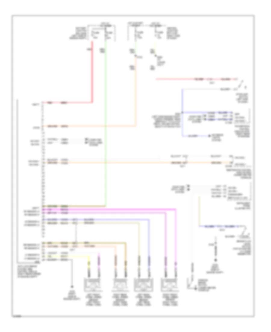
ANTI-LOCK BRAKES
Anti-lock Brakes Wiring Diagram for Ford Fiesta S 2011
List of elements for Anti-lock Brakes Wiring Diagram for Ford Fiesta S 2011:
- Anti-lock brake system (abs) control module (right rear corner of engine compt)
- Battery junction box (bjb) (left side of engine compt)
- Bpp
- Brake fluid level switch (top of master cylinder reservoir)
- Brk fluid lvl sw
- C175b
- C210
- C211
- C310b
- Cbp22
- Cca26
- Central junction box (cjb) (right side of dash)
- Computer data lines system
- Exterior lights system
- Fuse 10a
- Fuse 20a
- Fuse 40a
- Fuse 7.5a
- G108 (right side of engine compt)
- Gd123
- Gnd
- Hot at all times
- Hot in start or run
- Hs can +
- Hs can -
- Hs can+
- Hs can-
- Hs can2 +
- Hs can2 -
- Instrument panel cluster (ipc)
- Left front wheel speed sensor (left front wheel hubs)
- Left rear wheel speed sensor (left rear wheel hubs)
- Lf sensor hi
- Lf sensor lo
- Lr sensor hi
- Lr sensor lo
- Nca
- Parking brake switch (under center console)
- Parking brk
- Powertrain control module (pcm) (right rear of engine)
- Rca17
- Rca18
- Rca19
- Rca20
- Red
- Restraints control module (rcm) (under center console)
- Rf sensor hi
- Rf sensor lo
- Right front wheel speed sensor (right front wheel hubs)
- Right rear wheel speed sensor (right rear wheel hubs)
- Rr sensor hi
- Rr sensor lo
- S122
- S129
- S202 (left side engine compt wiring harness, near breakout to clutch pedal cruise control deactivator switch)
- S250 (w/ 4 door only)
- Sbb01
- Sbb28
- Stoplamp switch (left side of dash)
- Vbatt
- Vca03
- Vca04
- Vca05
- Vca06
- Vca23
- Vca24
- Vdb04
- Vdb05
- Vpwr
 English