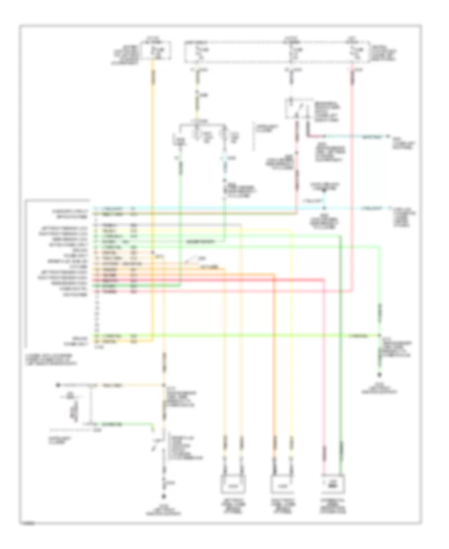
ANTI-LOCK BRAKES
Anti-lock Brake Wiring Diagrams for Ford Pickup F350 Super Duty 2001
List of elements for Anti-lock Brake Wiring Diagrams for Ford Pickup F350 Super Duty 2001:
- (engine sensor harn, left rear of engine compartment)
- (except sport)
- (main harness, near breakout to cluster)
- 239 (or 48)
- 4 x 4 high ind
- 4-wheel anti-lock brake system (4wabs) module (left side of engine compt)
- 4wabs ind ctrl
- Active 4-wheel input
- Anti- lock ind
- Battery junction box (on left side of engine compartment)
- Bias ckt
- Bpp switch feed
- Brake fluid level indicator switch (on brake fluid reservoir)
- Brake fluid level sw
- Brake pedal position (bpp) switch (under left side of dash)
- C146
- C236
- C242
- C243
- Central junction box (under left side of dash)
- Computer data lines system
- Data link connector (under center of dash)
- Diagnostic circuit
- Differential speed sensor (dss) (on rear axle)
- Fuse 10a
- Fuse 50a
- Fuse 5a
- G108 (left front radiator support)
- G200 (lower left kick panel)
- Ground
- Hot at all times
- Hot in run
- Ignition feed
- Instrument cluster
- Left front sensor (high)
- Left front sensor (low)
- Left front wheel 4wabs sensor (at wheel)
- Nca
- Not used
- Ohm
- Power input
- Processor micro-
- Rear sensor (high)
- Rear sensor (low)
- Red/pnk
- Right front sensor (high)
- Right front sensor (low)
- Right front wheel 4wabs sensor (at wheel)
- S106
- S170 (engine sensor harn, near breakout to 4wabs module)
- S171
- S172 (engine sensor harn, near breakout to 4wabs module)
- S208
- S229 (main harness, near breakout to cluster)
- S232 (main harness, near breakout to cluster)
- S265
- S297
- Tan/red
 English