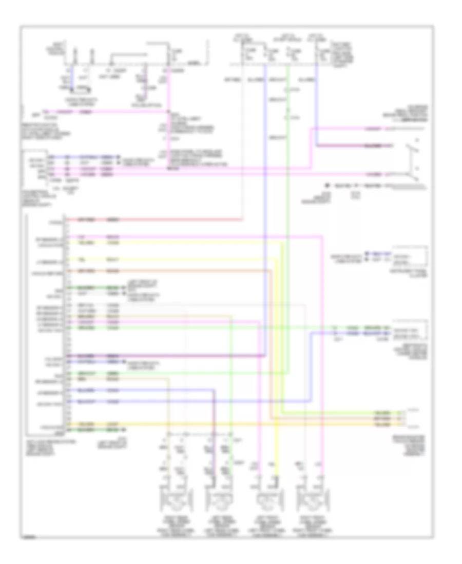
ANTI-LOCK BRAKES
Anti-lock Brakes Wiring Diagram for Ford Taurus SHO 2013
List of elements for Anti-lock Brakes Wiring Diagram for Ford Taurus SHO 2013:
- (left front of engine compt) g101
- (not used)
- (on brake pedal bracket) brake pedal position (bpp) switch
- (police option)
- 3.5l
- Anti-lock brake system (abs) module (left rear of engine compt)
- Battery junction box (bjb) (left side of engine compt)
- Body control module
- Bpp
- Bps
- Brake booster vacuum sensor (on brake booster assembly)
- C1381b
- C144
- C175b
- C210
- C211
- C2153c
- C2280b
- C2280f
- C299
- C3007
- C310b
- Cbb92
- Ccb08
- Ces09
- Computer data lines system
- Except 3.5l
- Fuse 10a
- Fuse 20a
- Fuse 50a
- Fuse 5a
- G101 (left front of engine compt)
- G105 (rear of engine compt)
- Gd120
- Gnd
- Hot at all times
- Hot in start or run
- Hs can +
- Hs can -
- Hs can yaw+
- Hs can yaw-
- Instrument panel cluster
- Junction wiring harness, near breakout to windshield wiper motor) s168
- Lca37
- Left front wheel speed sensor (left front wheel hub assembly)
- Left rear wheel speed sensor (left rear wheel hub assembly)
- Lf sensor hi
- Lf sensor lo
- Lr sensor hi
- Lr sensor lo
- Micro
- Mtr b+
- Nca
- Powertrain control module (rear of engine compt)
- Rca17
- Rca18
- Rca19
- Rca20
- Rca36
- Remote function actuator module (w/ intelligent access) (right side of dash)
- Restraints control module (under center console)
- Rf sensor hi
- Rf sensor lo
- Right front wheel speed sensor (right front wheel hub assembly)
- Right rear wheel speed sensor (right rear wheel hub assembly)
- Rr sensor hi
- Rr sensor lo
- Run
- S116 (3.5l)
- Sbb05
- Sbb43
- Vacuum pwr
- Vacuum return
- Vacuum sig
- Valve b+
- Vca03
- Vca04
- Vca05
- Vca06
- Vca23
- Vca24
- Vca36
- Vdb04
- Vdb05
 English