ANTI-LOCK BRAKES
Anti-lock Brake Wiring Diagrams for Ford Windstar 2000
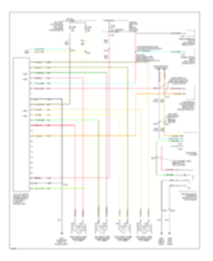
List of elements for Anti-lock Brake Wiring Diagrams for Ford Windstar 2000:
- (1999-2000) (2001)
- (dash panel to headlamp junction harn, near breakout to cooling fan)
- (main harn, near break- out to message center)
- (main harness, near breakout to inst cluster)
- (starter ground harn, top right of engine compt) s142 (1999-2000)
- Anti-lock brake control module (under vehicle, attached to hydraulic control unit)
- Battery junction box (left side of engine compartment)
- Brake pressure switch (left rear of engine compt)
- C116
- C127
- C195
- C240
- C241
- Central junction box (behind left side of dash)
- Computer data lines system
- Fuse 10a 15a
- Fuse 40a
- G106 (lower left front of engine compt)
- G200 (left kick panel)
- G201 (right side of dash)
- Hot at all times
- Hot in run
- Instrument cluster
- Left front wheel speed sensor (at wheel)
- Left rear wheel speed sensor (at wheel)
- Nca
- Not used
- Powertrain control module (behind right side of dash, through firewall)
- Red/pnk
- Right front wheel speed sensor (at wheel)
- Right rear wheel speed sensor (at wheel)
- S112
- S122 (2001) (dash panel harn, near breakout to brake pressure switch)
- S128
- S129
- S132
- S137
- S138
- S202
- S214
- S215
- S220
- S222
- Speed control servo (left side of engine compt)
- Traction assist/ parking aid disable switch (in glove box)
- V ref
 English