ANTI-LOCK BRAKES
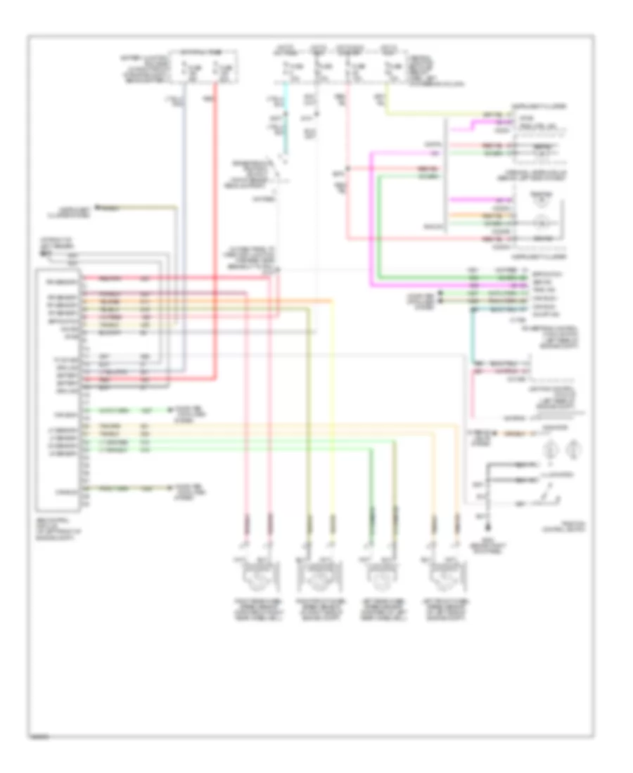
Anti-lock Brakes Wiring Diagram for Mercury Grand Marquis LS 2005
List of elements for Anti-lock Brakes Wiring Diagram for Mercury Grand Marquis LS 2005:
- (at front of left fender) g103
- (in dash panel to headlamp junction harness, near breakout to pcm) s103
- Abs control module (at left front of engine compt)
- Abs ind
- Analog
- Battery
- Battery junction box (bjb) (in right front of engine compt, behind battery)
- Bpp switch
- Brake pedal position switch (top of brake pedal support)
- C175b
- C2145b
- C220c
- C2220a
- C2220b
- Can bus +
- Can bus -
- Can bus+
- Can bus-
- Central junction box (cjb) (below dash, left of steering column)
- Computer
- Computer data lines system
- Data lines
- Digital
- Fuse 10a
- Fuse 20a
- Fuse 40a
- G203 (behind right kick panel)
- Ground
- Hot at all times
- Hot in run
- Hot in run or start
- Illumination
- Ind sig
- Indicator
- Instrument cluster
- Instrument cluster system
- Interior lights system
- Left front wheel speed sensor (at left side of engine compt)
- Left rear wheel speed sensor (forward of left rear wheelwell)
- Lf sensor+
- Lf sensor-
- Lighting control module (left rear of engine compt)
- Lr sensor+
- Lr sensor-
- On/off ind
- Powertrain control module (pcm) (left rear of engine compt)
- Red
- Red/pnk
- Rf sensor+
- Rf sensor-
- Right front wheel speed sensor (at right side of engine compt)
- Right rear wheel speed sensor (forward of right rear wheelwell)
- Rr sensor+
- Rr sensor-
- S101
- S201
- S237
- S276
- System
- Tc sw sig
- Trac ctrl ind
- Trac ind
- Traction control switch
- Vpwr
- Warning lamps module (behind left side of dash)
 English