COOLING FAN
Cooling Fan Wiring Diagram for Ford C-Max SE 2013

List of elements for Cooling Fan Wiring Diagram for Ford C-Max SE 2013:
- (engine wiring harness, near breakout to coolant pump)
- Active grille shutter (left front of engine compt)
- Battery junction box (bjb) (left side of engine compt)
- C1035c
- C134
- C140
- C175b
- C175e
- Cht
- Computer data lines system
- Cooling fan motor (behind radiator)
- Cylinder head temperature (cht) sensor (top of engine)
- Ect2
- Engine coolant temperature 2 (ect 2) sensor (phev) (right side of engine in coolant tubing)
- Engine cooling fan relay
- Fcv
- Fuse 10a
- Fuse 50a
- G105 (left side of engine compt)
- Gnd
- Hot at all times
- Hot w/ pcm power relay energized
- Hs can+
- Hs can-
- Lin
- Micro
- Nca
- Powertrain control module (pcm) (front of left front wheelwell)
- Pwr
- Re141
- Rh107
- S101
- S102
- S119
- S131
- Sig rtn
- Sigrtn
- Vbatt
- Vdb04
- Vdb05
- Vdn08
- Ve203
- Ve716
- Vpwr
- Water coolant pump 1 (lower left front of engine)
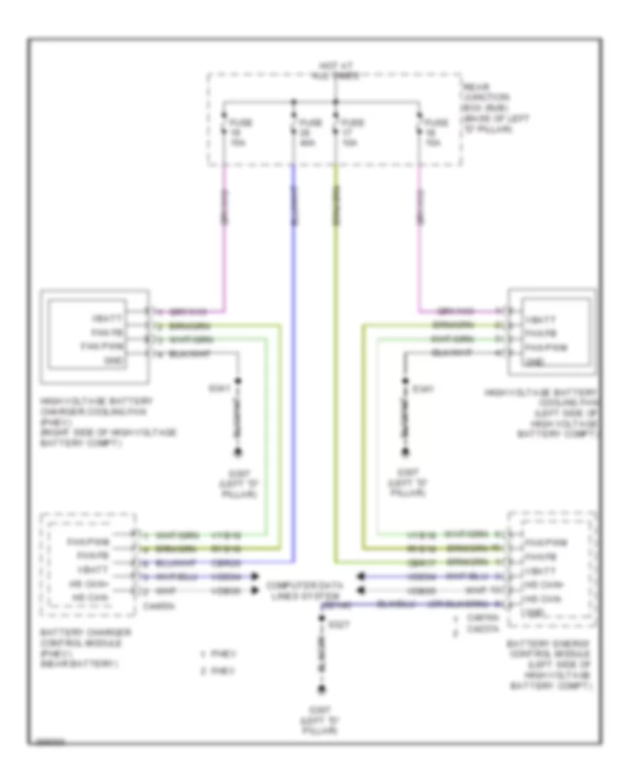
Hybrid Cooling Fan Wiring Diagram for Ford C-Max SE 2013
List of elements for Hybrid Cooling Fan Wiring Diagram for Ford C-Max SE 2013:
- Battery charger control module (phev) (near battery)
- Battery energy control module (left side of high voltage battery compt)
- C4237a
- C4455a
- C4816a
- Cbr17
- Cbr26
- Computer data lines system
- Fan fb
- Fan pwm
- Fhev
- Fuse 10a
- Fuse 15a
- Fuse 40a
- G307 (left "d" pillar)
- Gd145
- Gnd
- High voltage battery charger cooling fan (phev) (right side of high voltage battery compt)
- High voltage battery cooling fan (left side of high voltage battery compt)
- Hot at all times
- Hs can+
- Hs can-
- Phev
- Rear junction box (rjb) (base of left "d" pillar)
- Ryb18
- S327
- S341
- Vbatt
- Vdb04
- Vdb05
- Vyb18