COOLING FAN
2.0L
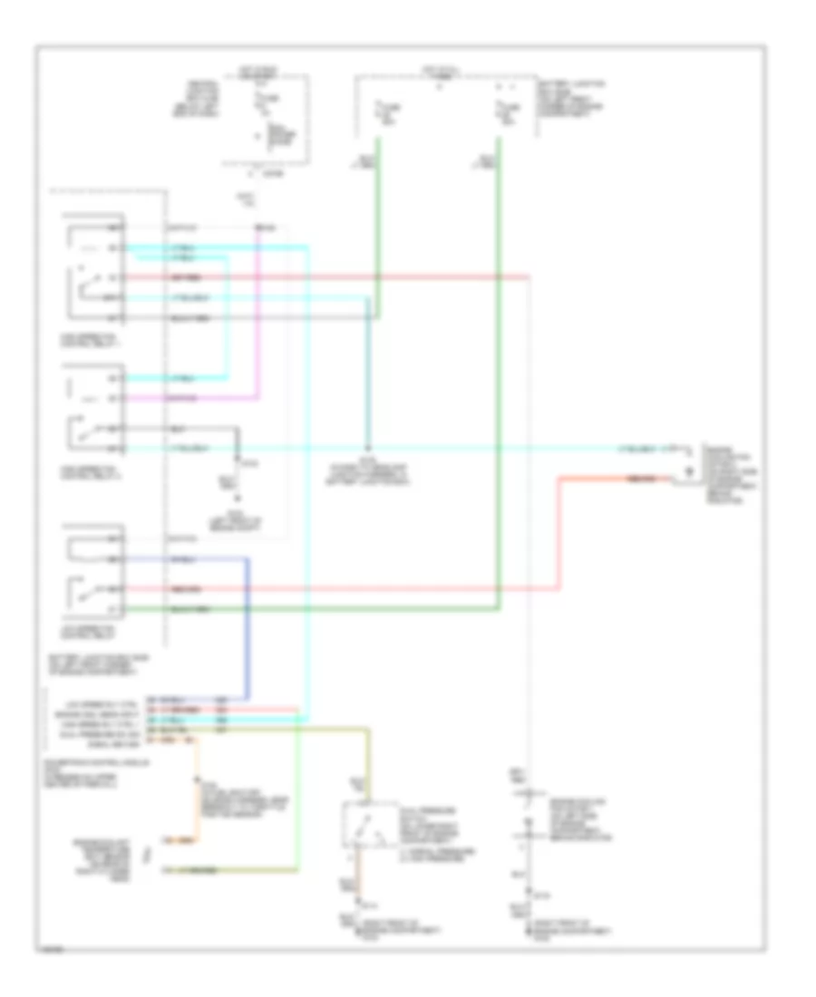
2.0L, Cooling Fan Wiring Diagram for Ford Escape 2004

List of elements for 2.0L, Cooling Fan Wiring Diagram for Ford Escape 2004:
- (1: normal pressure) (2: high pressure)
- (in dash to headlamp junction harness, in battery junction box) s127
- (left front of engine compartment) g104
- (right front of engine compartment) g102
- (right front of engine compartment) g103
- Battery junction box (bjb) (on left front corner of engine compartment)
- C270b
- Central junction box (cjb) (below left end of dash)
- Cyl temp sensor input
- Cylinder head temperature sensor (on right front of cylinder head)
- Dual pressure sw sig
- Dual pressure switch (on lower right front of engine compartment)
- Engine cooling fan motor 1 (on left side of engine compartment, behind radiator)
- Engine cooling fan motor 2 (on right side of engine compartment, behind radiator)
- Fuse 3a
- Fuse 40a
- High speed fan control relay 1
- High speed rly ctrl 1
- Hot at all times
- Hot in run or start
- Low speed fan control relay
- Low speed rly ctrl
- Med speed rly ctrl
- Medium speed fan control relay
- Pcm power diode
- Powertrain control module (pcm) (in recess on upper center of firewall)
- S114
- S116
- S128
- S132
- S144
- S154 (in fuel shut-off solenoid harness, near breakout to fuel injector 4)
- Signal return
3.0L
3.0L, Cooling Fan Wiring Diagram for Ford Escape 2004
List of elements for 3.0L, Cooling Fan Wiring Diagram for Ford Escape 2004:
- (1: normal pressure) (2: high pressure)
- (right front of engine compartment) g102
- (right front of engine compartment) g103
- 87a
- Battery junction box (bjb) (on left front corner of engine compartment)
- C270b
- Central junction box (cjb) (below left end of dash)
- Dual pressure sw sig
- Dual pressure switch (on lower right front of engine compartment)
- Engine cool sens input
- Engine coolant temperature (ect) sensor (on rear of right cylinder head)
- Engine cooling fan motor 1 (on left side of engine compartment, behind radiator)
- Engine cooling fan motor 2 (on right side of engine compartment, behind radiator)
- Fuse 3a
- Fuse 50a
- G104 (left front of engine compt)
- High speed fan control relay 1
- High speed fan control relay 2
- High speed rly ctrl 1
- Hot at all times
- Hot in run or start
- Low speed fan control relay
- Low speed rly ctrl
- Pcm power diode
- Powertrain control module (pcm) (in recess on upper center of firewall)
- S114
- S116
- S128
- S132
- S145 (in dash to headlamp junction harness, in battery junction box)
- S154 (in fuel shut-off solenoid harness, near breakout to throttle position sensor)
- Signal return