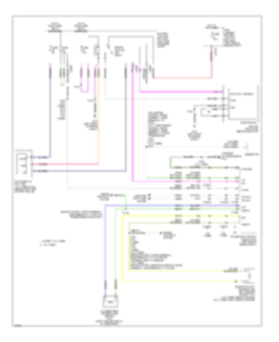
COOLING FAN
Cooling Fan Wiring Diagram for Ford Escape SE 2014
List of elements for Cooling Fan Wiring Diagram for Ford Escape SE 2014:
- (2.5l: engine control wiring assembly, near breakout to c145) (2.0l turbo: engine control wiring assembly, near breakout to 6f35 transmission) (2.5l) s115 (2.0l turbo) s107
- (engine control wiring assembly, near breakout to ignition transformer capacitor 1)
- (top rear of transmission) g104
- 1.6l turbo
- 2.0l turbo
- 2.5l
- Active grille shutter (1.6l turbo & 2.5l) (behind right end of front grille)
- Battery junction box (bjb) (left side of engine compt)
- C1035c
- C1381b
- C1381e
- C1551b
- C1551e
- C1617h
- C175b
- C175e
- Cbb08 (or cbb32)
- Cht
- Computer data lines system
- Cooling fan motor (behind radiator)
- Cylinder head temperature sensor (2.5l) (right center side of cylinder bank)
- Ect
- Electronics
- Engine controls system
- Engine coolant temperature (ect) sensor (except 2.5l) (1.6l turbo: rear of engine) (2.0l turbo: right rear of engine)
- Engine cooling fan relay
- Except 1.6l turbo
- Fan ctrl variable
- Fcv
- Fuse 10a
- Fuse 15a
- Fuse 50a
- Fuse 5a
- G107 (left front of engine compt)
- Gd120
- Generator
- Gnd
- High current battery junction box (bjb) (left side of engine compt)
- Hot at all times
- Hot w/ pcm power relay energized
- Hs can +
- Hs can -
- Lin
- Nca
- Powertrain control module (pcm) (left side of engine compt)
- Pwr
- Pwr gnd
- Re405
- Re454 (or re329)
- S103 (2.0l turbo) s112 (2.5l) s131 (1.6l turbo)
- S108 (2.0l turbo) s123 (1.6l turbo) (2.0l turbo: engine control wiring assembly, near breakout to intake air temperature (iat) sensor) (1.6l turbo: engine control sensor extension wiring assembly, near breakout to c1026)
- S125 (1.6l turbo)
- S147
- S148
- S149
- S176
- Sigrtn
- Vdb04
- Vdb05
- Vdn06 (or vdc46) (or vdn08)
- Ve203
- Ve712
- Ve716
- Vpwr
 English