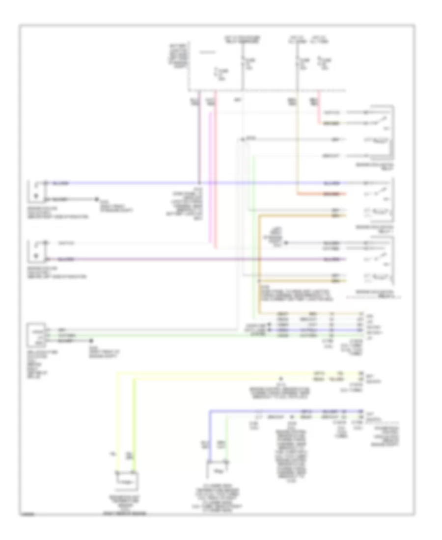
COOLING FAN
Cooling Fan Wiring Diagram for Ford Taurus SHO 2013
List of elements for Cooling Fan Wiring Diagram for Ford Taurus SHO 2013:
- (2.0l turbo & 3.5l twin turbo)
- (2.0l turbo)
- (3.5l twin turbo)
- (3.5l)
- (left front of engine compt) g101
- Battery junction box (bjb) (left side of engine compt)
- C1381b
- C1381e
- C175b
- C175e
- C192
- Cec07
- Cec08
- Cht
- Computer data lines system
- Cylinder head temperature sensor (3.5l & 3.5l twin turbo) (3.5l: front of right cylinder head) (3.5l turbo: rear of right cylinder head)
- Ect
- Engine coolant temperature sensor (2.0l) (right rear of engine)
- Engine cooling fan motor 1 (behind left side of radiator)
- Engine cooling fan motor 2 (behind right side of radiator)
- Engine cooling fan relay
- Engine cooling fan relay 1
- Engine cooling fan relay 2
- Fuse 15a
- Fuse 25a
- Fuse 40a
- G100 (right front of engine compt)
- Gnd
- Grille shutter actuator (3.5l) (behind right center of grille)
- Hfc
- Hot at all times
- Hot w/ pcm power relay energized
- Hs can +
- Hs can -
- Lfc
- Lin
- Powertrain control module (pcm) (rear of engine compt)
- Re405
- Re454
- S109 (3.5l: engine control sensor & fuel charge wiring harness, near breakout to fuel injector 2) (3.5l twin turbo: engine control sensor & fuel charge wiring harness, near breakout to c123)
- S113 (engine control sensor & fuel charge wiring harness, near breakout to coil on plug 2)
- S119
- S142 (dash panel to headlamp junction wiring harness, near breakout to battery junction box)
- S155 (dash panel to headlamp junction wiring harness, near breakout to high current battery junction box)
- Sig rtn
- Vdb04
- Vdb05
- Vdn06
- Ve712
- Ve716
- Vpwr
 English