CRUISE CONTROL
Cruise Control Wiring Diagram for Ford Econoline E150 1999
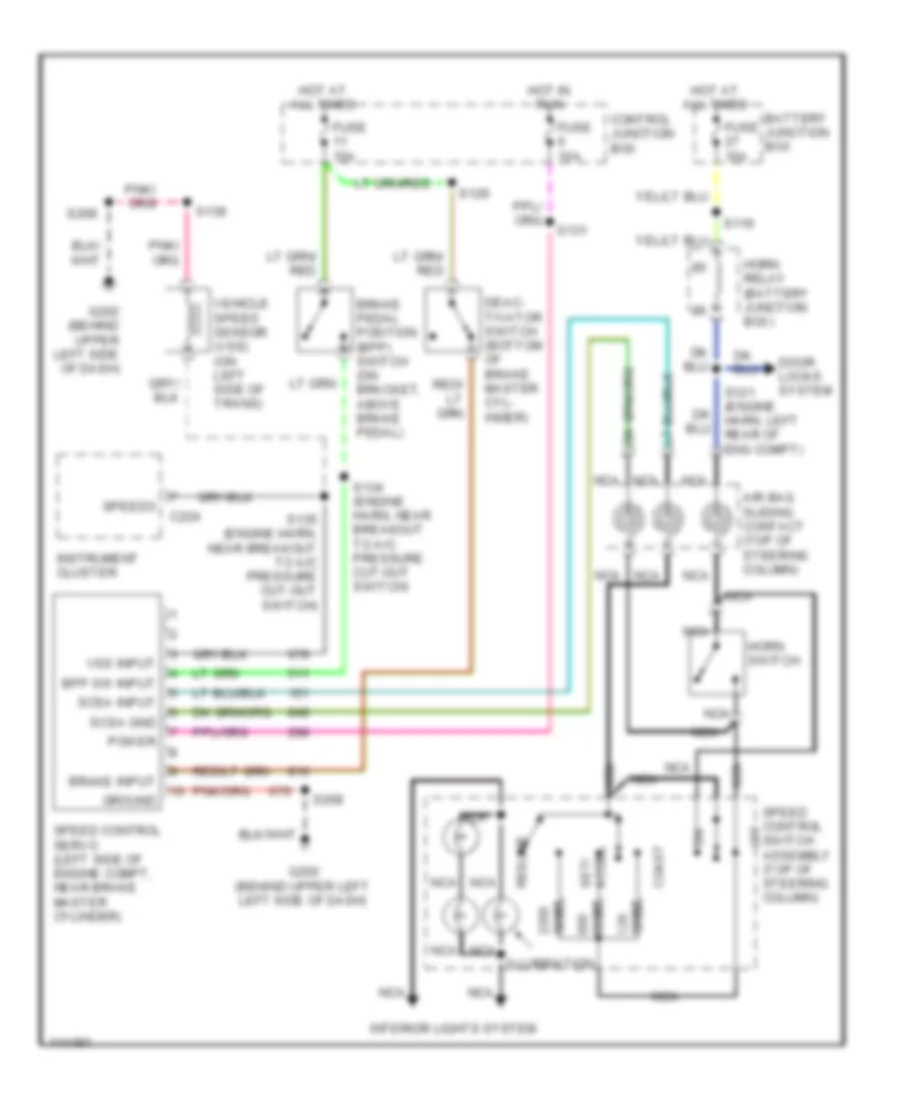
List of elements for Cruise Control Wiring Diagram for Ford Econoline E150 1999:
- Accel set/
- Air bag sliding contact (top of steering column)
- Battery junction box
- Bpp sw input
- Brake input
- Brake pedal position (bpp) switch (on bracket, above brake pedal)
- C224
- Coast
- Control junction box
- Deac- tivator switch (bottom of brake master cyl- inder)
- Door locks system
- Fuse 10a
- Fuse 15a
- G202 (behind upper left left side of dash)
- G202 (behind upper left side of dash)
- Ground
- Horn relay (battery junction box)
- Horn switch
- Hot at all times
- Hot at all times
- Hot in run
- Illumination
- Instrument cluster
- Interior lights system
- Nca
- Off
- Ohms
- Power
- Resume
- S116
- S121 (engine harn, left rear of eng compt)
- S129
- S131
- S134 (engine harn, near breakout to a/c pressure cut-out switch)
- S135 (engine harn, near breakout to a/c pressure cut-out switch)
- S139
- S268
- Scsa gnd
- Scsa input
- Speed control servo (left side of engine compt, near brake master cylinder)
- Speed control switch assembly (top of steering column)
- Speedo
- Vehicle speed sensor (vss) (on left side of trans)
- Vss input
 English