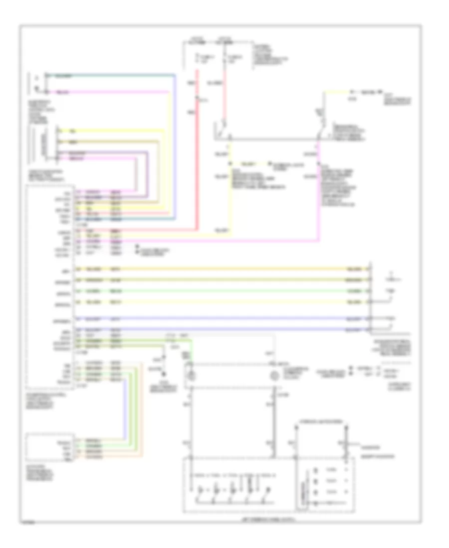
CRUISE CONTROL
Cruise Control Wiring Diagram for Ford Expedition EL XL 2014
List of elements for Cruise Control Wiring Diagram for Ford Expedition EL XL 2014:
- Accelerator pedal position sensor (top of accelerator pedal assembly)
- App1
- App2
- Apprtn
- Apprtn2
- Appvref
- Appvref2
- Automatic transmission (right rear of transmission)
- Battery junction box (bjb) (center front of engine compt)
- Bpp
- Bps
- Brake pedal position switch (top of brake pedal assembly)
- C175b
- C175e
- C175t
- C210
- C218a
- C218b
- Ce412
- Ce426
- Ces09
- Cet22
- Clockspring (steering column)
- Cls17
- Computer data lines system
- Electronic throttle control (etc) motor (top rear of engine)
- Etc ref
- Etc rtn
- Except navigator
- Exterior lights system
- Fuse 41 10a
- Fuse 43 15a
- G107 (right rear of engine compt)
- G108 (right rear of engine compt)
- Gd113
- Hot at all times
- Hs can +
- Hs can -
- Illumination
- Instrument cluster (ic)
- Interior lights system
- Kapwr
- Le134
- Le136
- Le137
- Left rear of engine compt) (navigator: engine compt harness,
- Left steering wheel switch
- Navigator
- Near breakout to vehicle dynamics module)
- Off
- Oss
- Powertrain control module (pcm) (right rear of engine compt)
- Pwr gnd
- Re134
- Re136
- Re137
- Red
- Res08
- Resume
- Ret24
- S102
- S103
- S114
- Sbb41
- Sccs
- Sccsrtn
- Set (+)
- Set (-)
- Solid state
- Tacm+
- Tacm-
- Throttle position sensor (tps) (on throttle body)
- Tp1
- Tp2
- Tr-gnd
- Tr-p
- Tss
- Vdb04
- Vdb05
- Ve701
- Ve702
- Ve818
- Ve819
- Ves10
- Vet26
- Vet33
 English