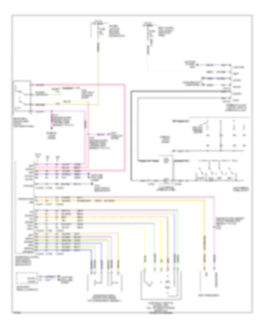
CRUISE CONTROL
Cruise Control Wiring Diagram for Ford F-150 STX 2014
List of elements for Cruise Control Wiring Diagram for Ford F-150 STX 2014:
- (engine control sensor wiring harness, near breakout to c180) (3.5l) s104
- (left side of dash) g202
- (or vet26)
- 3.5l
- 3.7l
- 5.0l & 6.2l
- 6r80 transmission
- Accelerator pedal position (app) sensor (top of brake pedal assembly)
- App1
- App2
- Apprtn
- Apprtn2
- Appverf2
- Appvref
- Battery junction box (bjb) (front of engine compt)
- Body control module (bcm) (right kick panel)
- Bpp
- Bps
- Brake pedal position (bpp) switch (left side of dash)
- C1381b
- C1381e
- C1381t
- C1551b
- C1551e
- C175b
- C175e
- C175t
- C218b
- C218c
- C2280a
- C2414a
- C2414d
- Ccb08
- Ce412
- Ce426
- Ces09
- Clockspring (steering wheel)
- Cncl/ rsm
- Computer data lines system
- Electronic throttle control (etc) (6.2l: top rear of engine) (except 6.2l: top front of engine)
- Etcref
- Etcrtn
- Except 3.5l
- Exterior lights system
- Fuse 10a
- Fuse 15a
- G100 (right side of engine compt)
- G102 (left front of engine compt)
- Gd113
- Gd133
- Hot at all times
- Hs can +
- Hs can -
- Hs can+
- Hs can-
- Instrument panel cluster (ipc)
- Interior lights system
- Le111
- Le134
- Le136
- Le137
- Left steering wheel switch
- Logic gnd
- Nca
- On/off
- Oss
- Powertrain control module (pcm) (right rear of engine compt)
- Pwr gnd
- Re134
- Re136
- Re137
- Re407
- Ret04
- S112 (engine control sensor wiring harness, near breakout to c110)
- S167 (engine control sensor wiring harness, near breakout to c110)
- Sbp23
- Sccrtn
- Sccs
- Set+
- Set-
- Shift interlock system
- Sigrtn
- Steering column control module (steering column)
- Tacm+
- Tacm-
- Tp1
- Tp2
- Tss/oss vpwr
- Vbatt
- Vdb04
- Vdb05
- Ve701
- Ve702
- Ve818
- Ve819
- W/ 5-button message center
 English