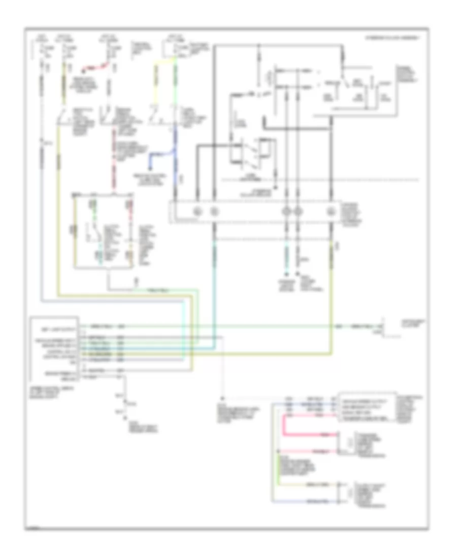
CRUISE CONTROL
Cruise Control Wiring Diagram for Ford Pickup F150 2000
List of elements for Cruise Control Wiring Diagram for Ford Pickup F150 2000:
- (main harn, near breakout to instrument cluster) s297
- A/t
- Accel
- Air bag sliding contact (top of steering column)
- Battery junction box
- Brake pedal position (bpp) switch (under left side of dash)
- Brake press in
- C160
- C234
- C236
- C242
- C243
- Central junction box
- Clutch pedal position (ccp) switch (on clutch pedal arm)
- Clutch pedal position (ccp) switch jumper (left side of dash)
- Coast
- Control sw gnd
- Control sw in
- Deactiva- tion switch (left rear corner of engine compt)
- Esof
- Fuse 15a
- Fuse 20a
- Fuse 5a
- G105 (rear of right fender apron)
- G203 (lower right kick panel)
- Ground
- Horn relay (in battery junction box)
- Horn switches
- Hot at all times
- Hot in run
- Ign
- Instrument cluster
- Interior lights system
- M/t
- Nca
- Off
- Ohms
- Oss sensor output
- Output shaft speed (oss) sensor (on left side of transmission)
- Pnk
- Powertrain control module (on right side of engine compt)
- Rear anti- lock brake system (rabs) module
- Red
- Remote control alarm and lock system
- Resume
- S102
- S112
- S138 (engine sensor harn, right rear corner of engine compartment)
- S143 (engine sensor harn, near breakout to windshield wiper motor)
- Set lamp output
- Set/
- Signal return
- Speed control servo (in left side of engine compt)
- Speed control switch assembly
- Steering column assembly
- Steering column ground
- Transfer case sp sen
- Transfer case speed sensor (at left rear of transmission)
- Vehicle speed input
- Vehicle speed output
 English