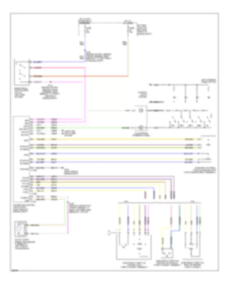
CRUISE CONTROL
Cruise Control Wiring Diagram for Ford Pickup F250 Super Duty 2009
List of elements for Cruise Control Wiring Diagram for Ford Pickup F250 Super Duty 2009:
- 4.6l
- 5.4l
- Acceleration pedal position sensor (app) (top of brake pedal assembly)
- App1
- App2
- Battery junction box (bjb) (front of engine compt)
- Bpp
- Bps
- Brake pedal position (bpp) switch (left side of dash)
- C175b
- C175e
- C175t
- Ccb08
- Ce412
- Ce426
- Ces09
- Clockspring (steering wheel)
- Computer data lines system
- Ectref3
- Electronic throttle control (etc) (throttle body assembly)
- Electronic throttle control motor (etc) (throttle body assembly)
- Electronic throttle position sensor (throttle body)
- Etcref
- Etcref2
- Etcrtn
- Etcrtn2
- Etcrtn3
- Fuse 15a
- Fuse 20a
- G100 (right side of engine compt)
- Gd113
- Hot at all times
- Hot w/ pcm power relay energized
- Hs can+
- Hs can-
- Interior lights system
- Le134
- Le136
- Le137
- Left steering wheel switch
- Nca
- Off
- Oss
- Output shaft speed (oss) sensor (4 speed a/t) (left side of transmission)
- Powertrain control module (pcm) (right rear of engine compt)
- Pwr gnd
- Re134
- Re136
- Re137
- Re406
- Res
- Res08
- S112 (engine control sensor wiring harness, near breakout to front center of engine compt)
- S146 (backup lamp switch wiring harness, to rear lamp feed near breakout to c140)
- Scc srtn
- Sccs
- Set+
- Set-
- T sigrtn
- Tacm+
- Tacm-
- Tp1 ns
- Tp2 ps
- Vdb04
- Vdb05
- Ve701
- Ve702
- Ve818
- Ve819
- Ves10
- Vet26
 English