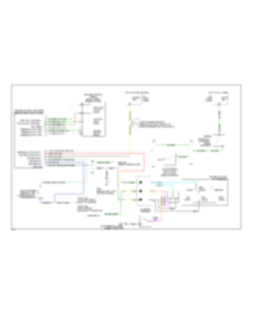
CRUISE CONTROL
Cruise Control Wiring Diagram for Mercury Tracer 1995
List of elements for Cruise Control Wiring Diagram for Mercury Tracer 1995:
- (behind left top
- (behind right cowl panel)
- (behind top left side of i/p
- (left side of
- (lower rear of
- (near wiper motor)
- (on brake
- (on clutch
- (on steering wheel
- (right front
- (top left front
- 1.8l
- 1.9l
- 110/140
- 15a
- 20a
- 40/78
- 400,000
- 500,000
- A/t
- Accel
- Assembly
- Brake
- Brake/clutch sw in
- Clutch pedal
- Coast
- Control sws input
- Cruise control
- Cruise control amplifier
- Dk orn
- Engine on transaxle)
- Feedback pot pos
- Feedback pot sig
- Fender apron)
- Front of engine)
- Fuse
- G110 (1.8l)
- G130 (1.9l)
- G200
- G207
- Ground
- Horn
- Horn relay
- Hot at all times
- Hot in start or run
- I/p
- Joint connector c213
- Lt gn/rd
- M/t
- Meter
- Near harness routing shield)
- Of cowl panel)
- Off
- Ohms
- On/off sw
- Panel
- Pedal
- Pedal support)
- Position sw
- Power input
- Resume
- Sensor (vss)
- Servo
- Set/
- Slipring
- Sol feed
- Stop
- Support)
- Sw assembly
- Tan
- Transmission)
- Under horn pad)
- Vac sol
- Vacuum sol control
- Vehicle speed
- Vent sol
- Vent sol control
- Vss ground
- Vss signal
 English